VFD Analog Input for Frequency Control
The analog signals used in the industrial control process are generally standardized, such as 0~10V, 0~20mA, 4~20mA, etc., which can greatly solve the problem of signal compatibility, and also provide equipment for the expansion of use. Convenience.
Our VFD also supports analog signal input control. Let me introduce the use of 4-20mA to control the frequency of the VFD.
Preparation work
Use 4~20mA analog to adjust the frequency of the VFD: CI, GND and JP3 terminals, jumper JP3 to the I terminal, use the FWD and COM terminals to start and stop the VFD, and connect the signal generator directly to the CI of the VFD and GND. Press the yellow button to start and stop the VFD.

Set VFD parameters
Set the frequency given mode P0.01=6 (4~20mA given).
Set the given mode of frequency P0.01=6 (given by 4~20mA).
P0.03=1 (terminal running command channel).
P0.03=1 (terminal running command channel).
P1.06, CI channel gain.
P1.06, CI channel gain.
P1.07, CI minimum given amount (V).
P1.07, CI min given (V).
P1.08, the frequency (Hz) corresponding to the minimum CI setting.
P1.08, Corresponding freq. to CI min given (Hz).
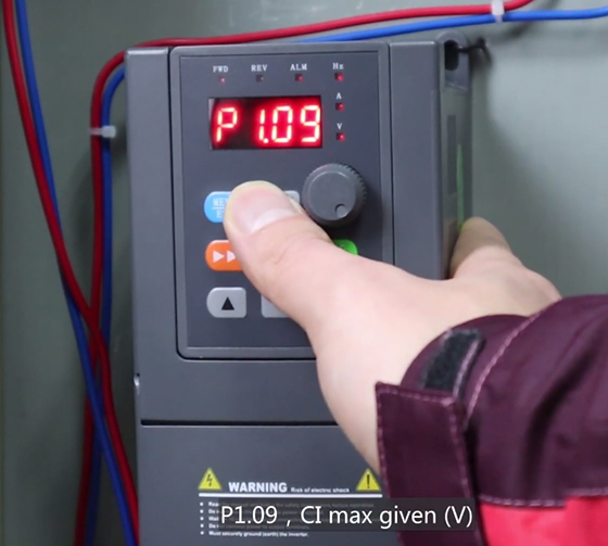
P1.09, CI maximum given amount (V).
P1.09, CI max given (V).
P1.10, the frequency (Hz) corresponding to the maximum CI setting.
P1.10, Corresponding freq. to CI max given (Hz).

Start test
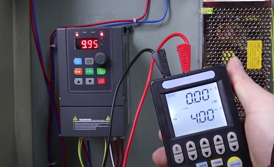
Press the start button and the FWD indicator lights up. The signal generator outputs a 4mA signal, and it is found that the VFD already has a 10Hz frequency output.

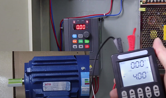
Modify the parameter P1.07=2, and start the VFD again. At this time, input a 4mA analog current to the VFD, and the VFD frequency is 0Hz.

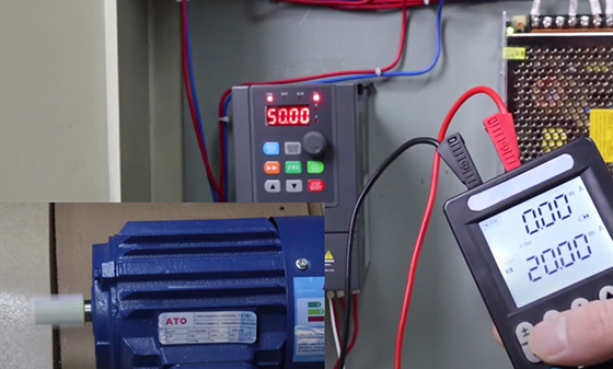
Increasing the VFD input current increases the VFD output frequency and the motor speed becomes faster. When the input reaches 20mA, the VFD output frequency is the maximum frequency of 50Hz.
As the input current is reduced, the VFD output frequency decreases accordingly.

You can also watch the video below to know more detail about VFD analog input (4-20mA) for frequency control.

