How to Wire and Test a Photoelectric Sensor?
Photoelectric sensors utilize light beams emitted from a transmitter to detect the presence, absence, or distance of objects within their sensing range. They consist of two main components: the transmitter and the receiver. The transmitter emits a modulated light beam, often infrared or visible light, towards the target area. The receiver detects the reflected light or absence thereof, depending on the sensor's mode of operation. In this article, we will walk you through the wiring and testing process of ATO's M18 photoelectric sensor.
Components
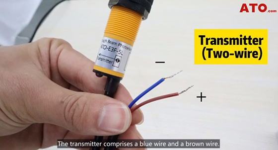
The photoelectric sensor is comprised of two main parts: a transmitter and a receiver. The transmitter section features a blue wire, which functions as the negative terminal, and a brown wire, serving as the positive terminal. On the other hand, the receiver is equipped with three wires: a positive wire, a negative wire, and a black wire designated for transmitting the output signal. This configuration allows the beam photoelectric sensor to effectively transmit and receive signals, enabling accurate detection and measurement capabilities.
Wiring Process
To ensure proper testing, we will use a 24V sensor tester.
Transmitter Wiring
- Connect the brown wire (positive) of the transmitter to the 24V positive terminal of the testing unit.
- Connect the blue wire (negative) of the transmitter to the negative terminal of the testing unit.
Receiver Wiring
- Follow the same wiring procedure for the receiver, connecting the positive and negative wires accordingly.
- Screw the black wire (output signal) of the receiver to the Sensor Outputs #1 terminal.
Testing the Sensor
With the photoelectric sensor powered on, proceed to test its functionality by placing an object within its detection range.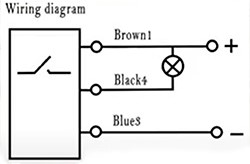
- Observe the sensor's reaction to the object presence.
- Verify the sensor's proper functioning through the output indicator on the tester.
The accompanying wiring diagram illustrates the internal workings of the photoelectric sensor's detection mechanism.
If you find anything unclear in this blog, you can check out the following video for further clarification.
