How to Use VFD to Maintain Stable Water Pressure?
In this blog, we will delve deeply into configuring the advanced features of the Variable Frequency Drive (VFD) to ensure and maintain stable water pressure within your water supply system. By exploring each step of the setup process meticulously, ATO industrial automation aim to provide a thorough understanding of how to optimize the VFD settings for efficient and reliable operation in controlling water pressure.
Wiring Setup
Let's start with the wiring setup. The model we are using is ATO’s VFD GK3000. Begin by connecting the power supply to the terminal block on the control board as depicted in the provided diagram. Once the power supply is connected, proceed to establish the basic electrical connections by linking the output terminals directly to the motor.
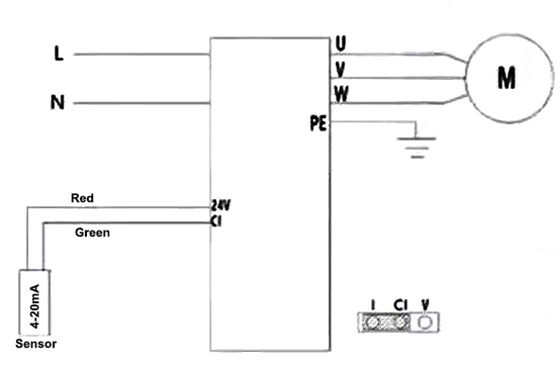
Next, for control and sensor configuration, ensure the control output is set to operate within the 4-20mA range by adjusting the jumper to the designated pin I. Additionally, enable continuous monitoring of water levels by connecting the level sensor to the 24V power supply. These steps will lay the foundation for effective control and monitoring of your water supply system using the specified components.
Parameter Settings
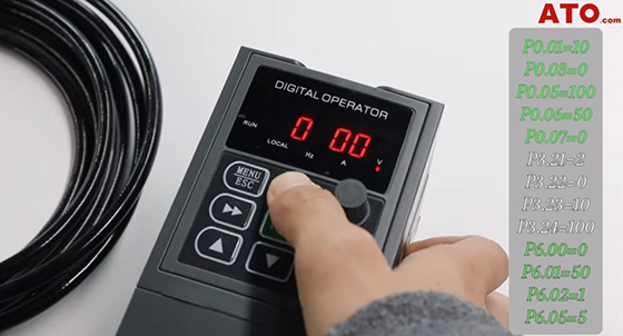
To access and modify parameters, press the "Menu" button to enter the parameter menu. From there, use the "Up" and "Enter" keys to browse the menu to reach and adjust the desired settings. Next, we will introduce the specific parameter settings.
P0 Group Settings
- P0.01: Set to 10.
- P0.03 (Control Terminals Running Command Channel): Press "Enter" to access the parameter and ensure it is set to 0.
- P0.05 (Maximum Frequency Setting): Set Maximum Frequency to 100.
- P0.06 (Upper Limit Frequency Setting): Set Upper Limit Frequency to 50.00.
- P0.07 (Lower Frequency Limit): Set Lower Frequency Limit to 0.00.
P3 Group Settings
- P3.21 (CI Minimum Input Voltage): Set CI Minimum Input Voltage to 2.
- P3.22 (CI Minimum Input Voltage): Set Minimum CI Corresponds to 0% to 0.
- P3.23 (CI Maximum Voltage Input): Set CI Maximum Voltage Input to 10.
- P3.24 (Maximum CI Corresponds to 100%): Set Maximum CI Corresponds to 100% to 100.
P6 Group Settings
- P6.00 (PID Set Channel Selection): Set PID Set Channel Selection to 0.
- P6.01 (PID Digital Set): Set PID Digital Set to 50.
- P6.02 (PID feedback channel CI): Set PID Feedback Channel CI to 1.
- P6.05 (Proportional Gain KP1): Set Proportional Gain KP1 to 5.
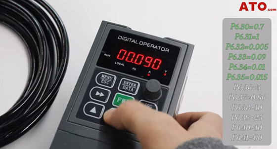
- P6.30 (Given Pressure): Set Given Pressure to 0.7.
- P6.31 (Maximum Pressure Value): Set Maximum Pressure Value to 1.000.
- P6.32 (Minimum Pressure Value): Set Minimum Pressure Value to 0.005.
- P6.33 (Alarm Pressure Value, Upper Limit): Set Alarm Pressure Value, Upper Limit to 0.09.
- P6.34 (Alarm pressure Value, Lower Limit): Set Alarm Pressure Value, Lower Limit to 0.01.
- P6.35 (Wake-up Pressure Value): Set Wake-up Pressure Value to 0.015.
- P6.36: Modify P6.36 to 5. This function refers to the duration time of VFD’s full-frequency running against Wake-up Pressure.
- P6.37: Change P6.37 to 0.06. This parameter asks you to set the Sleep Pressure Level Threshold. When the water pressure exceeds this value, the frequency gradually decreases until reaching the sleep frequency.
- P6.38: Adjust P6.38 to 10. This parameter requires you to decide for how long you’d like the water pressure to maintain at the sleep pressure level.
- P6.39: Modify P6.39 to 25. It’ s asking you to set the sleep frequency.
- P6.40: Change P6.40 to 10 so that the VFD will keep running at sleep frequency for 10s.
- P6.41: Modify P6.41 to 00. In this way, when the VFD "wakes" up, the sleep pressure is set to match the actual pressure and the VFD will run at the sleep frequency.
Testing and Operation
During testing, ensure to activate the monitoring feature by navigating to parameter b0.47 and confirming its activation. This feature allows real-time monitoring of crucial system metrics.
Throughout the test, the VFD will operate according to the configured parameters: When the water pressure reaches the wake-up level of 0.015 MPa, the motor will initiate full-frequency operation for a duration of 5 seconds. Upon reaching the sleep level of 0.060 MPa, the frequency will gradually decrease to 25 Hz and maintain this level for 10 seconds. Subsequently, the VFD will enter sleep mode until the pressure once again drops to the wake-up level, thus repeating the operational cycle.
These steps ensure that the VFD functions effectively to maintain consistent water pressure, providing reliable performance in your water supply system. This concludes our guide on setting up the VFD for stable water pressure control.
If you don’t understand anything about this article, you can refer to the following video.
