How to Use Digital Multimeter for Circuit Measurements?
A multimeter is an essential tool for anyone working with electrical circuits. It allows precise measurement of various electrical parameters such as voltage, current, resistance, and continuity. In this tutorial, ATO industrial automation will guide you through the process of using a digital multimeter effectively for circuit measurements.
Setup
Insert the black probe into the COM port and the red probe into the port labeled for multiple parameters. The black 10A port on the left is only used when measuring large currents.
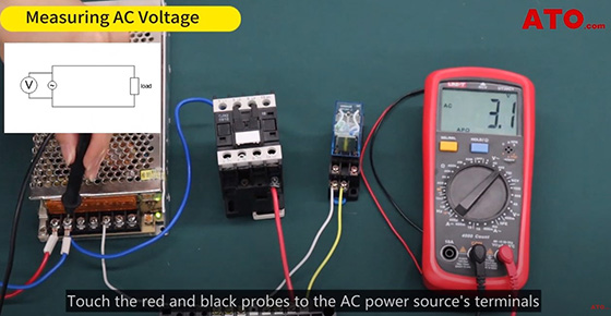
Measuring AC Voltage
Start by selecting the appropriate range on the multimeter dial, typically from high to low. For AC voltage measurement, we're using the 400V AC range. Touch the red and black probes to the AC power source's terminals and read the value displayed on the digital multimeter.
Measuring NCV (Non-Contact Voltage Detection)
The next step is NCV or non-contact voltage detection. Simply bring the front end of the meter close to the object being tested. The more indicators or bars displayed and the higher the frequency of the beeping sound or blinking LED, the stronger the electric field detected. No detection or indication means no AC voltage field. You can also toggle the circuit's on/off state to observe the corresponding changes.
Measuring DC Voltage
Set the multimeter dial to the appropriate DC voltage range, such as 40V. Connect the red and black probes to the positive and negative terminals of the DC power source respectively. Read the displayed value on the digital multimeter, indicating the DC voltage.
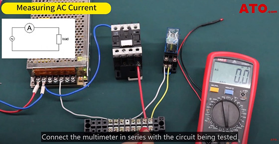
Measuring AC Current
Switch the multimeter to the suitable AC current range, such as 400mA. Connect the multimeter in series with the circuit being tested and read the displayed value, representing the AC current.
Measuring DC Current
Measuring DC current follows a similar procedure as AC current measurement. However, if the red and black probes are reversed, a negative value will be displayed. Ensure the correct probe orientation for a positive reading. Swap the positions of the probes to obtain a positive reading. For instance, if the reading shows 42.1mA, it represents the DC current.
Continuity Testing
Continuity testing is an essential feature of a digital multimeter, used to check for connectivity in a circuit. Touch the probes to the respective points in the circuit. If the circuit is continuous, the digital multimeter will emit a continuous beep, and the red LED will turn on. If there is a break in the circuit, the multimeter will remain silent.
Diode Testing
Switch to diode testing mode using the SELECT/REL button. Connect the probes to the diode's terminals. "OL" indicates an open or reversed diode, while a numerical value indicates a normal diode. This allows you to test diodes and identify any abnormalities or faults.
Measuring Resistance
Select the resistance range, such as 4kΩ. Touch the probes to the component or coil being measured for resistance. Read the displayed value for the resistance measurement.
By mastering these measurements with your digital multimeter, you'll be equipped to troubleshoot, diagnose, and analyze electrical circuits effectively. Watch the following video for further learning.
