How to Set Up and Install Ultrasonic Flow Meter?
The ultrasonic flow meter is a cutting-edge device designed for accurate flow measurement in various applications. Included with the ultrasonic flowmeter are various accessories, such as transducers, mounting brackets, clamps, and coupling agents. It offers a user-friendly interface for easy navigation and configuration. The flow meter consists of a main unit, transducers, and installation accessories, which ATO will guide you through in this setup process.
Ultrasonic Flow Meter Wiring
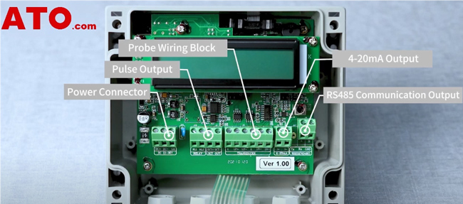
Unscrew all the screws from the cover. After removing the cover, we can see that the flow meter is mainly divided into the display section and the wiring section. The wiring section consists of the following parts:
- Power Connector - this ultrasonic flow meter is generally connected to a 24V DC power supply.
- Pulse Output.
- Transducer Wiring Block, including the terminals for the upstream and downstream transducers.
- 4-20mA Output.
- RS485 Communication Output.
Next, move on to connecting the power supply and the sensor. For the power, connect the 24V+ to DC+ and the negative terminal to DC-. For the transducers, connect the red wire to the positive terminal, the black wire to the negative terminal, and the shielded wire to the E (Earth) terminal.
Ultrasonic Flow Meter Setting
Once the wiring is complete, power on and set up the flow meter. Press the menu key and enter code 11 to access the pipeline parameter settings, and the following step takes the wall-mounted ultrasonic flow meter with pipe DN150 as an example.
Setting Pipeline Parameters:
- Pipe Outer Diameter: DN150 pipe, input 159mm and press Enter to confirm.
- Pipe Wall Thickness: Input the wall thickness, choose 5mm, and confirm.
- Pipe Material: Select the appropriate material (e.g., carbon steel, stainless steel, PVC). In this case, select carbon steel and confirm.
- Transducer Type: Choose between Standard (clamp-on) or plug-in (Type-B45) transducers based on your needs. For this example, select Standard and confirm.
- Transducer Mounting Method: Choose the mounting method (V, Z, or N). For this setup, select the V method and press Enter.
- Transducer Spacing: The flow meter will display the calculated installation distance between the two transducers.
- Saving Parameters: Confirm to save all the entered parameters.
- Viewing Flow Rate: Press the menu key and enter code 02 to view the instantaneous flow rate and the cumulative flow in Run mode.
3 Steps for Installing Transducers
- Step one, apply coupling agent on the sensor.
- Step two, place the sensor with the coupling agent in close contact with the pipe and gently rub it a few times to eliminate any gaps between the sensor and the pipe.
- Step three, secure the sensor to the pipe using a clamp. The other sensor can be installed in the same way.
Transducers Installation Notes: Two sensors must be installed consistently in orientation and aligned in a straight line and the installation distance between the two sensors should strictly follow the distance calculated by the flow meter.
By following these steps, you can successfully set up and install your ultrasonic flow meter. This guide ensures accurate measurement of flow rates and reliable performance of your flow meter system. For more details, please watch the following video.
If you have any further questions or need additional support, refer to the user manual or contact the ATO online shop for assistance.
