How to Set the Analog Output of Load Cell Amplifier?
Load cell amplifiers are critical devices that enhance the functionality of load cells by converting their low-level electrical signals into amplified outputs suitable for accurate measurement and analysis. These amplifiers not only boost the signals but also condition them by filtering noise and ensuring linearity. Their versatility makes them essential in industries such as manufacturing, automotive, and aerospace. In this guide, we’ll walk through how to set the analog output of a digital load cell amplifier.
Wiring Configuration
Left Side Connections
- SIG+ and SIG: These are the signal ports where the amplifier receives signals from the load cell.
- EXE+ and EXE: These ports are used to power the load cell.
Right Side Connections
- P+ and P: These ports supply 24V DC to the amplifier.
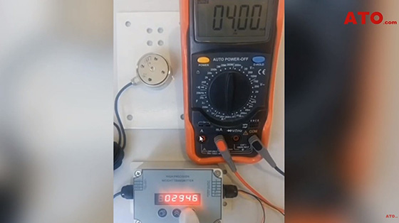
Current Output Measurement
This particular amplifier features a 4-20mA output. To test with a multimeter, first insert the red probe into the mA range port of the multimeter. Then, connect a wire from the red probe to the I port of the amplifier (where I represents current). Next, insert the black probe into the COM port and connect the other end to the P- port of the amplifier, which serves as the common terminal with the power source.
Setting Up the Analog Output
Assuming the amplifier and load cell provide accurate measurements, follow these steps to configure the analog output:
- Enter Parameter Settings: Hold the first button on the left for 3 seconds to enter parameter settings.
- Zero Calibration (Parameter 08 CZ): For zero calibration, press the first button again to locate Parameter 08 (CZ), then press and hold the second button to access it. Adjust the display value until the multimeter reads 4.00mA, using the second button to navigate the input position and the third button to modify the value, fine-tuning it until you achieve a reading of 4.00mA.
- Full Load Calibration (Parameter 09 CF): For full load calibration, press the first button to locate Parameter 09 (CF), then press and hold the second button to enter. Adjust the full load value to 20.00mA, using the second button to shift the input position and the third button to adjust the value until the multimeter displays 20.00mA.
- Load Range Setting (Parameter 10 Cr): For load range setting, press the first button to locate Parameter 10 (Cr), then press and hold the second button to enter. For our load cell rated at 10 kg, input 10000 into the amplifier.
- Exit Parameter Settings: Once all settings are configured, exit by holding the first button.
Verification
To verify the configuration, use a 1 kg weight. The instrument should read 1000g, corresponding to a current output of 5.6mA, which should match the reading on the multimeter.
Conclusion
By following these steps, you can successfully set up and calibrate your load cell amplifier for accurate measurements. Proper calibration is crucial for reliable data, ensuring your system operates effectively. You can visit ATO.com to obtain more load cell options. If you have any questions, you can watch the following video to further understand.
