How to Rotate BLDC Motor for Electric Car?
In addition to the brushless DC motor is often used in industrial automation, we often see its application in electric vehicles. And what we want to introduce today is an infrastructure that it uses in electric vehicles.
Materials:
- 24VDC brushless DC motor
- 24VDC brushless DC motor driver (controller)
- 24VDC power supply
- Start button switch
- Forward and reverse switch
- Acceleration pedal

Of course, this time we use the DC power supply powered by the mains. In the actual application process, we recommend using the power supply provided by the battery, because this is related to the energy recovery of the braking system.
Now we connect the brushless DC motor circuit according to the following circuit diagram:

As can be seen from the picture, all our wiring is connected around the controller, and it has the common point of all DC brushless motors, that is, it has the Hall wiring part (Hall A, B, C, 5V, GND) ), and the power wiring part of the motor.
The aluminum shell motor control lead part of our ATO has been fully equipped, including the logo and aerial plug, so there is no need to worry too much about the wiring of this part.
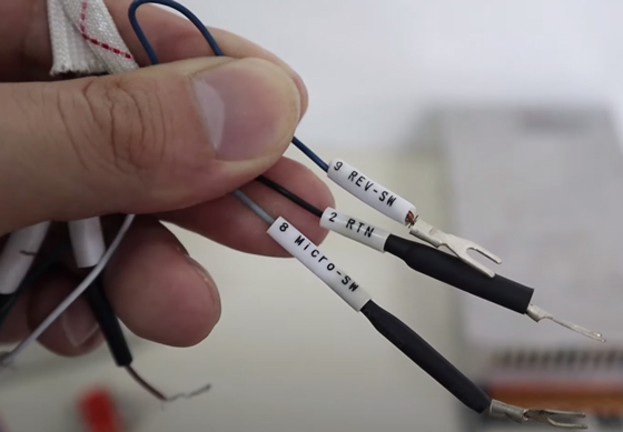
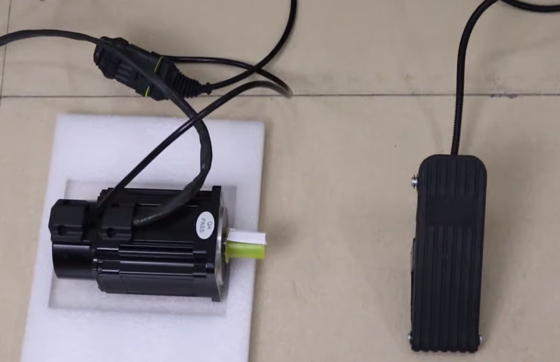
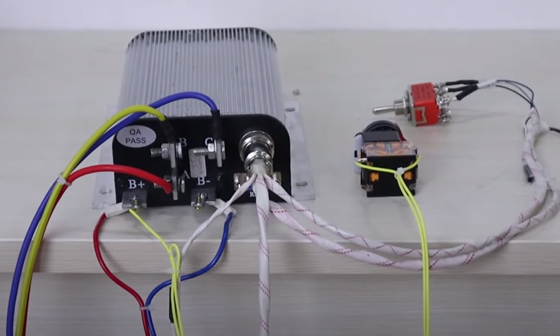
Power on, the enable switch, PWR and B+ need to be turned on before the motor rotates.
The drive line first lights up red, and then automatically jumps to green.
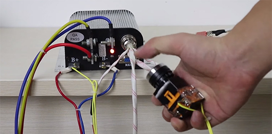
Press the start button and the controller indicator will turn green from red.
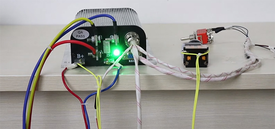
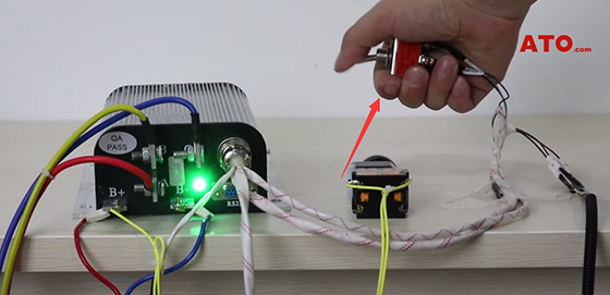
Switch the direction of rotation.
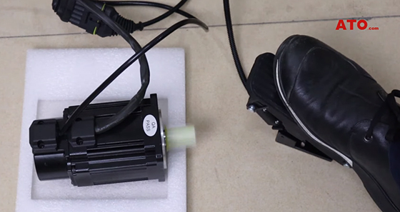
Apply pressure to the pedals and the motor accelerates movement.
Tips: There are two important parts to understand for an ATO brushless DC motor system:
- The wiring between the motor and the controller, including the power line and the Hall line.
- Wiring the control part of the controller, enable switch, rotation direction switch, foot pedal.
We can replace the foot pedal with a handle-type analog control switch, or other acceleration hardware of the same style.
You can also view the video below to know more about how to rotate the BLDC motor for electric car.

