How to Control the Frequency of VFD Based on PLC?
A programmable logic controller (PLC) or programmable controller is an industrial computer that has been ruggedized and adapted for the control of manufacturing processes, such as assembly lines, machines, robotic devices, or any activity that requires high reliability, ease of programming, and process fault diagnosis. A variable-frequency drive (VFD) is a type of motor drive used in electro-mechanical drive systems to control AC motor speed and torque by varying motor input frequency and, depending on topology, to control associated voltage or current variation.
How to control the VFD's frequency based on PLC? Today we will show you by using ATO HMI, ATO PLC, PLC analog module and ATO-VFD.
Analog output control system structure established by HMI through PLC

HMl and PLC communicate with Host-link protocol through RS232 interface

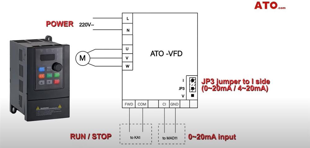
Wiring diagram
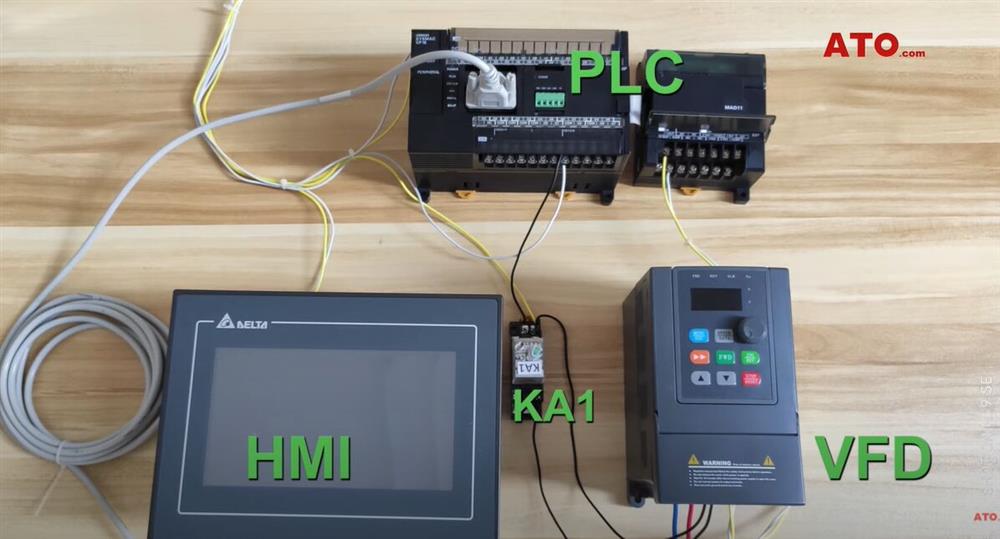
The system wiring is completed like this. KA1 is controlled by PLC, and KA1 controls RUN and STOP of VFD.
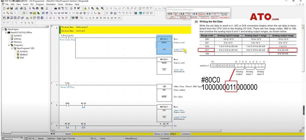
PLC programming
- The first PLC program moves the control instruction of 0-20mA output into the special register area 1, 102 is the output register bit of the analog expansuion unit.
- D10 is used as the VFD input frequency data storage area and is cleared when the PLC command is executed for the first time.
- T005 is the data execution time. W0.00 is the external executiotrigger condition of VFD RUN (It existes in the HMI program).
- When W0.00 is triggered, the data of D100 will be transferred to the 102.
- At the same time, the 101.00 port of the PLC is triggered, and the external relay KA1 coil is pulled in. (The VFD terminal run command starts to execute)
- WO.01 is the external trigger condition of VFD STOP. (It exists in the HMl program)
HMI programming
- The first step is create a data entry box. Double-click the created data input box to edit the attributes. The data input box is directly connected to the D10 storage area of the PLC (VFD frequency data storage area). That is, this position in the PLC program.
- Then set the data limit of the input box (minimum 0Hz, maxumum 60Hz). Gain, which controls the magnification of the input data.
- When the input is 20mA (input maximum frequency is 60Hz), the corresponding command data is 6000.For example: input 60Hz in the data input box, and the value actually input to the D10 storage area after zooming in 100 times is 6000. The output value of the PLC analog module corresponding to 6000 is 20mA. We can also set the font format of the input box.
- Setting of RUN key: the RUN key corresponds to W0.00 in the PLC program.
- Create the STOP button in the same way: the STOP key corresponds to W0.01 in the PLC program.
- The external relay is controlled by W0.00 and W0.01.
- After completion, download all programs to HMI.

Wiring
- MAD11 outputs analog signals to C1 and GND of the VFD.
- The RUN and STOP of VFD are controlled by KA1 and KA1 receives VFD control.
- HMI communicates with PLC through RS232 interface.
Power-on testing
- Enter 30Hz in the frequency input box and press RUN.
- The KA1 relay is triggered, and the VFD runs at 30Hz after receiving the signal output by the PLC analog module.
- Input 60Hz, VFD runs at 60Hz frequency.
- After pressing the STOP button, KA1 is closed and VFD stops running.

You can view the video below to learn more about how to control a VFD frequency based on PLC.
