How to Control the Forward and Reverse of Stepper Motor?
In this guide, we will explore how to achieve forward and reverse control of a stepper motor using a PLC (Programmable Logic Controller) and HMI (Human-Machine Interface). Below are the setup and programming steps required for precise control.
Components Introduction
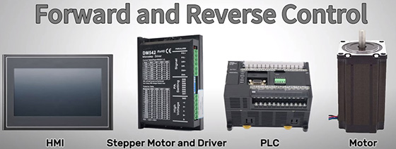
To complete this project, you will need the following major equipment, all of which can be found on ATO.com. The main equipment is as follows:
- PLC (Omron CP1E N4ODT-D)
- HMI (Delta DOP 107CV)
- Stepper Motor and Driver
- 24VDC Power Supply (ATO Switching Power Supply)

System Wiring
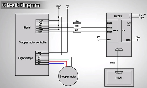
The PLC acts as the brain of the system, communicating with the HMI via RS232. The HMI provides a user-friendly interface for operators to monitor and interact with the system. The motor driver serves as the intermediary between the PLC and the stepper motor, with the PLC outputting pulse and direction signals to control the motor's rotation.
Circuit Diagram
Next, let’s take a quick look at the basic circuit diagram, along with specific wiring for the PLC and motor controller.

Driver Settings
The DIP switch settings on the controller, including Peak Current and RMS settings, should be configured to match the specifications of the stepper motor. The Pulse Output Revolution needs to be set to 400 pulses for one full rotation.
PLC Programming Overview
In this section, we’ll focus on the PLC programming necessary for controlling the stepper motor. The operation begins with pressing W0.00, which initiates the forward rotation of the motor. Releasing W0.00 will stop the motor. The SPED (Speed Output) command #0000 is used to set the pulse output to 0, while the output mode command #0100 activates continuous pulse output mode, allowing the motor to rotate clockwise at a frequency of 2400Hz.
When W0.00 is closed, the stepper motor rotates clockwise at 2400Hz. The Set Bit for this operation is defined as Q100.00. Upon releasing W0.00, the pulse frequency changes to 0Hz, effectively stopping the motor, and the Reset Bit is also set to Q100.00. This straightforward control mechanism ensures precise management of the motor’s forward motion.
The programming for reverse control is similar. The port is configured for pulse output, and pressing W0.01 causes the stepper motor to run counterclockwise at 2400Hz, with the Set Bit designated as Q100.01. Releasing W0.01 stops the motor by resetting the frequency to 0Hz, while the Reset Bit updates to Q100.01, providing a reliable means of controlling the motor’s reverse operation.
HMI Configuration
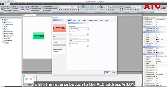
In the HMI configuration, right-click to create a momentary button for the start function in the HMI software. Double-click the button area to edit button properties. In this example, only two buttons are needed—one for forward motion and one for reverse motion. The forward button is linked to the PLC address W0.00, while the reverse button is linked to W0.01. You can also edit the text and add graphics for the buttons.

Practical Operation
Now let’s initiate the system and demonstrate the operation in practice. Select the desired direction on the HMI interface for the stepper motor. The motor will respond to the commands sent from the PLC via the motor driver, with the reverse button causing the motor to rotate counterclockwise and the forward button making it rotate clockwise.
By integrating PLC, HMI, and a motor driver for stepper motor control, you can achieve seamless forward and reverse operation with enhanced precision, reliability, and efficiency. This combination of technology optimizes industrial processes, making it a crucial approach for various automation applications. If there is anything you don't understand, watch the video below to learn more.

