How to Control Stepper Motor with HMI & PLC for Fixed Cycle Power Output?
In this article, we will explore how to integrate HMI (Human Machine Interface) with PLC (Programmable Logic Controller) to control the power output of a stepper motor based on a fixed cycle length. This approach allows for precise motor control and is ideal for applications that require stable and adjustable cycle outputs.
System Components
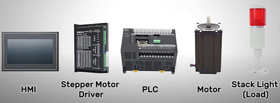
The system requires the following key components to achieve stepper motor control and power output management:
- HMI (Human Machine Interface): The interface for user input and operation, which helps monitor and control the entire system.
- Stepper Motor Driver: Receives pulse signals from the PLC and precisely controls the rotation of the stepper motor.
- PLC (Programmable Logic Controller): The central controller that manages the motor's action logic and communicates with the HMI and stepper motor driver.
- Stepper Motor: The motor that rotates according to the control signals from the PLC and outputs power during the specified cycle.
- Stack Light (Load): Provides a visual indication of the load output status based on the motor's operation.
These components work together to achieve precise stepper motor control and efficient load output management.

System Structure and Operation
The system structure involves the integration of HMI and PLC to control the stepper motor driver. The motor driver regulates the motor’s movement, and the PLC manages the logic for motor operation and load output.
The process begins with user input through the HMI, where the operator sets the number of pulses for the motor’s rotation. The PLC processes these inputs and controls the stepper motor’s movement. After the motor completes the specified rotation, the PLC triggers the load output. The cycle then repeats, continuing to manage the motor’s movement and load output until manually stopped.
Wiring and Configuration
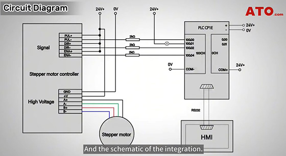
After selecting the necessary components, proper wiring is essential to ensure that all components communicate effectively. The PLC must be connected to the stepper motor driver, HMI, and load output. Correct wiring ensures that the motor operates according to the PLC’s commands, and that the load output is triggered appropriately.
The stepper motor driver needs to be configured with parameters such as pulse frequency and cycle length. These settings ensure that the motor rotates the correct distance and that the load output is managed based on the motor's movement. Accurate configuration of these parameters is crucial for the system's smooth operation.

PLC Programming and Control Logic
PLC programming forms the core of the system, determining how the motor operates and how the load output is triggered. The PLC must be programmed to control the stepper motor's rotation and load output based on the pulse count input from the HMI.
The process begins with the closing of W0.00 in the PLC to start the motor. The motor rotates at a frequency of 1000Hz in the clockwise direction for a fixed distance. This distance is stored in the D100 data register in the PLC, corresponding to the pulse count entered by the user via the HMI. Once the motor completes the specified pulse count, the PLC sets the A280.03 completion flag to ON, signaling the system to output the load.
After the load output is completed, the system will send a positive edge signal to the PLC, prompting the motor to rotate again, continuing the cycle. The motor will keep rotating and outputting power until the W0.01 input is closed, at which point the motor stops by operating at 0Hz, and the load output is disconnected.
HMI Configuration and User Interaction
The HMI interface allows users to interact with the PLC and control the stepper motor. The configuration includes various buttons and input fields for starting, stopping, and adjusting the motor's rotation distance.
The RUN button is a latching button that is connected to W0.00 on the PLC. Pressing this button starts the motor. The STOP button is a toggle button that is connected to W0.01 on the PLC, stopping the motor and disconnecting the load when pressed.
The HMI also includes a pulse count input field linked to the PLC's D100 data register, where users can set the number of pulses that define the motor's rotation distance. A Load Indicator Light is connected to Q100.01 output in the PLC. When the load is OFF, the light will be red, and when the load is ON, the light will be green, providing a visual indicator of the system’s operational status.
System Operation and User Flow
During system operation, the user begins by entering the desired pulse count in the HMI. This pulse count determines how far the motor will rotate before triggering the load output. When the RUN button is pressed, the stepper motor begins rotating at the specified frequency (1000Hz) and completes the set distance. Upon completion, the load is triggered.
Once the load output is completed, the motor resumes rotating in a continuous loop. The system will keep running until the user presses the STOP button, which will stop the motor and disconnect the load. If the user wants to change the motor's rotation distance during operation, they can modify the pulse count on the HMI, allowing for flexible control of the system’s output.
Conclusion
By integrating HMI and PLC, this system offers precise control over a stepper motor, allowing for power output regulation based on a fixed cycle length. Whether used in manufacturing, testing, or automated operations, this solution provides a reliable and efficient method to control motor movement and load output in a continuous or fixed cycle. You can watch the video below to further understand the specific operation.

