How to Control Motor with Push Button and VFD?
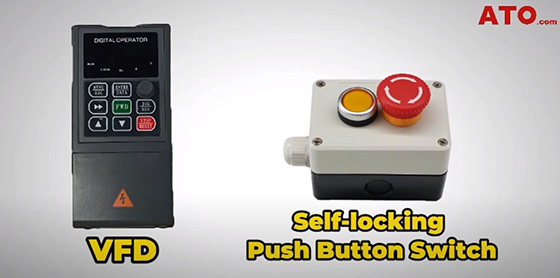
In today's article, we will demonstrate how to effectively control the operation of a motor using a self-locking push button switch and the ATO upgraded VFD model GK3000. This detailed guide aims to provide comprehensive insights into setting up and utilizing these components to achieve precise motor control in various industrial and commercial applications. Before beginning, ensure you have the necessary components ready: the VFD, a self-locking push button (latching switch), a motor and the required wiring materials.
Wiring Setup
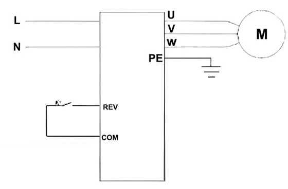
For the wiring setup, start by connecting the power supply to the VFD as per the circuit diagram provided. Proceed to wire the motor to the VFD using the U, V, W terminals. To install the latching switch, remove the VFD cover using a screwdriver to access its internals. Connect the normally open contacts of the latching switch to the designated terminals inside the VFD. Once connected, reassemble the VFD by replacing the cover and securing it with the four screws using a screwdriver. This completes the installation of the wiring setup for your motor control system.
Configuring Control Modes
We have the control mode with the function code P3.14 set for zero, which refers to two-line control mode 1 and its rationale is shown in the wiring diagram given here. The push button switch can be connected to either X1 (FWD) or X2 (REV) terminals of the VFD. In this example, we choose the REV terminal to control reverse rotation. And then adjust parameter settings on the VFD:
- Set P0.01 to 1 for frequency setting via panel potentiometer and to retain frequency data after power-off.
- Set P0.03 to 1 to enable external control.
- Set P3.01 to 2 to activate reverse motor rotation.
- Set P3.14 to 0 to enable 2-wire control mode, facilitating operation with a single push button.
Testing and Operation
After completing the wiring and parameter settings, it's time to perform a test run.
- Press the self-locking push button to power on the VFD. The motor should start running in reverse rotation as configured.
- Adjust motor speed using the potentiometer on the VFD panel.
- Press the button again to stop the motor, observe the instantaneous retention of frequency data on the VFD screen when power is cut off.
By following these steps, you can effectively control the operation of a motor using a self-locking push button and the VFD from ATO. This setup demonstrates the precise control capabilities of VFDs using external terminals, enhancing operational flexibility in industrial settings.
This tutorial not only provides practical guidance but also showcases the versatility and functionality of modern VFDs in industrial applications. Mastering these setups can significantly enhance motor control precision and operational efficiency in various industrial scenarios. Check out a more detailed technical video on:
