How to Connect Load Cell Display Controller to PC Software?
A load cell display controller is an essential device used to monitor and display weight measurements in various applications. These controllers work in conjunction with load cells, which are sensors that convert force or weight into an electrical signal. The display controller interprets this signal, providing a readable output, often in the form of weight readings on an LCD or LED screen. In this video, we've shown the step-by-step process for how to connect ATO 6 digit display controller to PC software. Below are the connection steps.
Step 1: Connect the RS485 adapter cable
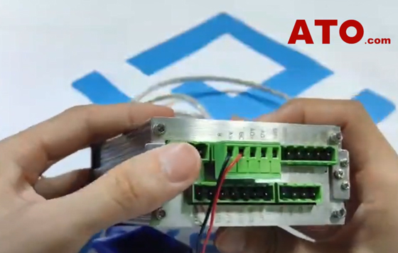
We connect the RS485 adapter cable to the 6 digit load cell display controller, with the red wire to A+ and the black wire to B-.

Step 2: Connect the load cell
Connect the load cell to the display controller and supply 24V power to the unit. After powering it on, press and hold the K1 key to access the parameter settings. Press K4 to change to the last input position. Press K3 to change the value to 1, then press K1 to save the modification.
Press K1 again to find parameter 31, which is initially set to 1. Press K3 to change it to 2 (1 = ModbusRTU, 2 = Active Send ASC). And press K1 to save.

Step 3: Connect the RS485 adapter cable to the PC
Then power off the instrument and restart to apply the changes. Connect the RS485 adapter cable and the encrypted USB flash drive to the computer.
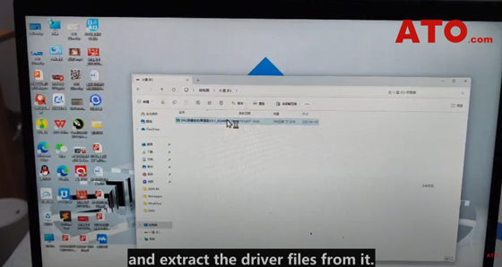
Open this PC, locate the newly installed USB drive, double-click to open it, find the compressed folder, and extract the driver files from it.
After extraction, the driver folder will appear in the DAQ folder. Double-click to open, find the file named CP210, double-click to open, locate CP210x64, double-click to start the installation, and select Allow to install. Double-click to open the software installation package, find the install application, and double-click to install it.
After installation, the desktop will display the DAQ Test System icon. Double-click to open, click Settings, and select ATO-DPM-DY800 in the device model dropdown in the top right corner. Refresh the serial port and select COM3, set the baud rate to 19200, click Connect Device, and if the green indicator lights up, it indicates a successful connection.

Step 4: Start receiving data
Click the Data Acquisition tab, and click "Start".
Now let’s apply pressure to the load cell, and the signal received by the instrument can be displayed in real-time through this software.
If you want to know more about this load cell display controller connection and software setup tutorial, please refer to the video below. Also, ATO Automation Store provides different types of digital display controllers for you to choose from.

