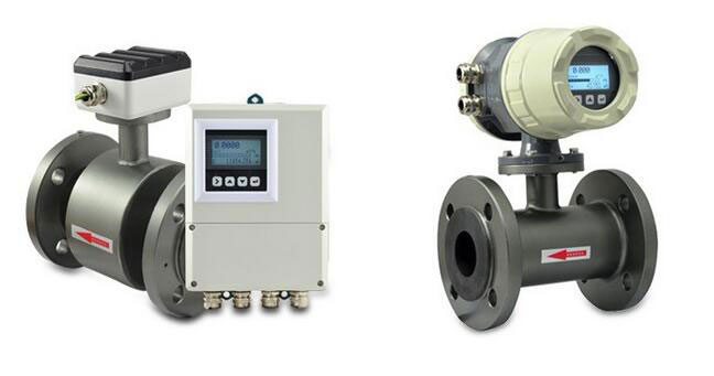
How Magnetic Flow Meter Works?
A magnetic flow meter, mag meter, or electromagnetic flow meter is a kind of instrument which measures the volume flow rate of the conductive fluid based on the principle of Faraday's Law of Electromagnetic Induction. At present, the magnetic flow meter with a large diameter is mostly applied to the water drainage and supply engineering, while the magnetic flow meter with a medium and small-size diameter is usually applied to the fluids, which are hard to measure or have high requirements, such as liquid-solid fluids. Based on the characteristics, the magnetic flow meter is widely used to monitor and control the paper pulp liquid and black liquid from the paper-making industry, ore pulp from the non-ferrous metallurgical industry, coal slurry from the coal preparation plant, highly-corrosive liquid from the chemical industry, and cooling water of the blast-furnace tuyere from the steel industry, and hydraulic handling of the pipeline coal at a long interval. The magnetic flow meter with a small or micro caliber is usually applied in the places with hygiene requirements, such as the medical industry, food industry, bioengineering industry, etc.
The magnetic flow meter conducts flow measurement according to Faraday’s law of electromagnetic induction. With a large measurable flow range, the ratio of the maximum flow rate to the minimum flow rate maintains above 20:1. The mag flow meter is suitable for wide range of industrial pipe diameter, and the maximum can reach up to 3m. The output signal and the measured flow are linear, and the magnetic flow meter has high measurement precision. It can effectively measure the flow rate of fluids with a conductivity more than 5μs/cm, such as acid solution, alkaline solution, saline solution, water, sewage, corrosive liquid, mud, ore pulp, and paper pulp. Nevertheless, the electromagnetic flow meter cannot be used to measure the flow of gases, steam and purified water.
After taking quick look at the magnetic flow meter, let’s come to the point and dive into the working principle.
When the conductor moves at cutting the magnetic line of force on the magnetic field, the induced electromotive force will be generated in the conductor. The value of the induced electromotive force is in direct proportion to the valid length of the conductor on the magnetic field, and the speed of the conductor which moves vertically to the direction of the magnetic field. Similarly, when the conductive fluid moves vertically on the magnetic field, and at a tangent direction of the magnetic line of force, the induced electromotive force will be generated on the electrode on two sides of the pipe. The direction of the induced electromotive force is determined by the right-hand rule, and the value of the induced electromotive force can be given by the following formula.
Ex = BDv ------ Eq. (1)
Ex - Induced electromotive force, V
B - Magnetic flux density, T
D - Inner diameter of the pipeline, m
v - Average flow rate of the fluid, m/s
The volume flow Qv, equals the product between the fluid flow rate v, and the pipeline cross-sectional area (πD2)/4, so let’s substitute Eq. (1) in.
Qv = (π D/4B)* Ex ------ Eq. (2)
As shown in Eq. (2), when the pipeline diameter D is given, and the magnetic flux density B remains unchanged, the measured volume flow rate and the induced electromotive force are linearly correlated. When an electrode is inserted into two ends of the pipeline, the induced electromotive force Ex can be introduced to measure the value of the electromotive force and to obtain the volume flow. According to Faraday’s law of electromagnetic induction, a pair of detection electrodes is installed on the pipe wall vertical to the measurement pipe axis and the magnetic line of force. When the conductive fluid moves along the measurement pipe axis, the conductive fluid is tangent to the magnetic line of force to generate the induced electromotive force. The induced electromotive force can be detected by two detection electrodes. The value of the induced electromotive force and the flow rate are in direct proportion to each other. The value of induced electromotive force is calculated in the below equation.
E = B·V·D·K
E-Induced electromotive force
K-Coefficient related to the magnetitic field distribution and axial length
B-Magnetic flux density
V-Average flow rate of the conductive fluid
D-Electrode spacing (to measure the diameter within the pipeline)
After that, the sensor of magnetic flow meter takes the induced electromotive force E as the flow signal, and transmits it to the converter. After signal processing, including amplification, transforming and filtering, the instantaneous flow rate and the integrated flow rate can be displayed in the dot-matrix liquid crystal screen with the backlight. The converter of the magnetic flow meter features the 4-20mA output, alarm output and frequency output, and is equipped with the RS-485 communication interface. It also supports the HART and MOBUS protocol.
Please be note that the parameters of different electromagnetic flowmeters are slightly different. For more details, please move to the product page of ATO magnetic flow meter. Please refer to the user manual before use.

