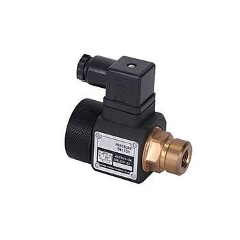
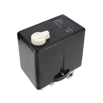
How does a Pressure Switch Work?
A pressure switch is an electrical contact device that drives a switch through the action of gas or liquid pressure. It is mainly composed of power or pressure sensitive components (feeling external pressure), mechanical linkage mechanism (transmitting pressure), micro switch (executed by normally open and normally closed contacts) and other parts. Understanding the working principle of the pressure switch helps us to use it better. The following will provide you with the knowledge of the working principle, application and adjustment method of the pressure switch.
Pressure switch work principle
The working principle of the pressure switch: When the pressure in the system is higher or lower than the rated safety pressure, the disc in the sensor moves instantaneously, and the switch joint is connected or disconnected by connecting the guide rod. When the pressure drops or rises to the rated recovery value, the disc resets instantaneously, and the pressure switch automatically resets, or in simple terms. When the measured pressure exceeds the rated value, the free end of the elastic element is displaced, and the switch is pushed directly or after comparison components, change the on-off state of the switch element, to achieve the purpose of controlling the measured pressure. The elastic components used in the pressure switch include single coil spring tube, diaphragm, and so on.
When the power element is driven by external gas or liquid and the pressure can overcome the elastic force of the compression spring, it can push the piston rod up to make the micro switch act (that is to say, the normally closed contact is disconnected and the normally open contact is closed), so as to control the circuit perform on-off function. When the external pressure disappears or the pressure is low, the piston will break away from the micro switch under the action of the spring to reset the contact system. The minimum pressure value of the pressure switch action is called the rated value of the pressure switch, and its size can be adjusted by the screw according to the actual use of the controlled object to meet the needs of different requirements and occasions.
Application of pressure switch
The pressure switch is a simple pressure control device, which uses a high-precision, high-stability pressure sensor and transmission circuit, and then uses a dedicated CPU modular signal processing technology to realize the detection, display, alarm and control signal of the medium pressure signal output. When the measured pressure reaches the rated value, the pressure switch can send out an alarm or control signal. It can be widely used in the measurement and control of the pressure of various gases and liquids in the fields of petroleum, chemical industry, metallurgy, electric power, water supply and so on.
Pressure switches are commonly used in paper machines, air compressors or pump sets. In such devices, we rely on pressure switches as safety devices, alarms or control elements in the system. Take an air compressor switch as an example: an ordinary air compressor consists of three main parts: a motor, a V-shaped air pump, and an air storage tank. The air compressor is equipped with a pressure switch, which can adjust the start and stop of the motor. By adjusting the pressure in the oil tank, the air compressor can rest. During the debugging process, the air compressor factory can set a certain start-stop pressure according to the requirements of different customers. For example, when the compressor starts, air is sucked inside by the pump, and when the pressure reaches the set value, the pressure switch stops the motor. When the pressure is lower than the set value, the air compressor starts again to keep the pressure in the oil tank within the pressure range.
How to adjust pressure switch?
The pressure switch is used for the pressure state of refrigerant or air, and its typical application is to display and control the pressure. When the accuracy of the set value is not high, it can be debugged according to the scale of the controller and the pressure gauge in the system. When the set value is high, please use a special pressure calibrator and precision pressure gauge for debugging. The switch can set two switching values, usually called upper limit switching value and lower limit switching value. The right adjusting screw on the top of the pressure switch directly adjusts the upper limit switch value, and the left adjusting screw on the top of the pressure switch is used to adjust the pressure difference of the switch. Their relationship is: upper limit switch value - voltage difference = lower limit switch value.
For example: the controlled pressure is required to be kept between 0.5 and 0.8Mpa:
Choose a pressure controller with a set value range of 0.1-1.0Mpa.
Turn the pressure adjustment screw on the right side of the top to make the pointer indicate 0.8Mpa (8kg or 8bar) on the scale, which is the upper limit switching value.
Turn the pressure adjustment screw on the left side of the top to make the pointer indicate 0.3Mpa on the scale, the lower limit switch value = the upper limit switch value - switch pressure difference = 0.8-0.3=0.5, and this value is the lower limit switch value.
Connect the terminal of the controller to the controlled electrical circuit.
PS: ① It is the public wiring. ③It is normally open output. ⑤ It is normally closed terminal output.
High voltage protection:
Connect ① to ⑤, when boosting normally, ①-⑤ is connected, ①-③ is not connected.
When the pressure rises to the set upper limit, that is, at 0.8Mpa, ①-⑤ is blocked, and ①-③ is connected.
When the pressure drops, ①③ is connected at this time, and the pressure drops to the lower limit set point, which is 0.3Mpa.
Switch to ①⑤ connected, ①-③ not connected. When the depressurization stops and the pressure rises, it will automatically cycle.
Low voltage protection:
The pressure is required to be lower than 0.1Mpa, and the pressure switch should be disconnected.
Turn the pressure adjustment screw on the right side of the top to make the pointer indicate 0.15Mpa on the scale, which is the upper limit switching value.
Turn the pressure adjustment screw on the left side of the top to make the pointer indicate 0.05Mpa of the scale, lower limit switch value = upper limit switch value - switch pressure difference = 0.15-0, 05 = 0.1, and this value is the lower limit switch value.
When the power is turned on and pressure is greater than 0.15Mpa, the device starts to work. When the pressure drops to 0.1Mpa, the lower limit of the pressure switch is switched, and the device will stop working to achieve the purpose of protection.
Precautions for using pressure switches:
The upper limit of the pressure setting value must be greater than the pressure difference setting value (pressure setting value - pressure difference setting value = lower limit initial value). For example, the upper limit is set to 8kg, and the pressure difference is set to 2kg. Then 8 kg was turned off. Start when the pressure drops to 6kg. If it is inaction, you should check the reason.
Make the setting value of the pressure switch consistent with the indication of the pressure gauge (if the pressure rises to the upper limit setting, the switch has not yet acted, that is, turn the pressure adjustment screw, fine tune to the switch action, and repeat the verification again), and perform the lower limit verification, the process is the same as above.

