Close
(0) Shopping cart
You have no items in your shopping cart.
Shopping Categories
    Filters
    Preferences
    Search
    Monday, November 25, 2024 11:59:58 PM

    How to Control the Brake with BLDC Motor Controller?

    one month ago
    #250 Quote
    Hello, everyone! Can you help me with the next questions about the BLDC motor controller ATO-BLDC-KBL?
    1. Can I use an external power supply (24 VDC) to energize the controller?
    2. How do I wire the brake to the controller?
    3. Do I need to signal one of the 14-pin connector to enable the brake? If so which pin and what type of signal (24V, 5V, etc.)?
    0
    one month ago
    #251 Quote
    Daniel wrote:
    Hello, everyone! Can you help me with the next questions about the BLDC motor controller ATO-BLDC-KBL?
    1. Can I use an external power supply (24 VDC) to energize the controller?
    2. How do I wire the brake to the controller?
    3. Do I need to signal one of the 14-pin connector to enable the brake? If so which pin and what type of signal (24V, 5V, etc.)?

    Hi Daniel,
    For your questions,
    1. No, the power supply of your controller can only match the voltage of the motor you purchased. In other words, if the motor you purchased is 48VDC, the input voltage of the controller should also be 48VDC, not 24VDC.
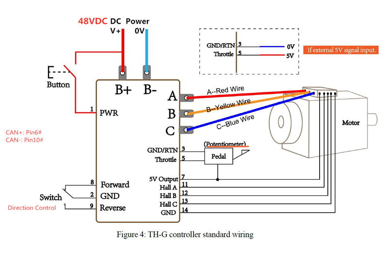
    2. Regarding the wiring of the controller, you can use the 1#PWR in the 14-pin connector to connect to the B+ terminal through a push button switch as the control signal of the controller. Please refer to the attached drawing.
    3. The control voltage of the brake is 24VDC. It can't be controlled by a controller, you can only control it individually through an external 24VDC voltage.
    0
    ATO.com
    one month ago
    #252 Quote
    ATO wrote:
    Hi Daniel,
    For your questions,
    1. No, the power supply of your controller can only match the voltage of the motor you purchased. In other words, if the motor you purchased is 48VDC, the input voltage of the controller should also be 48VDC, not 24VDC.
    2. Regarding the wiring of the controller, you can use the 1#PWR in the 14-pin connector to connect to the B+ terminal through a push button switch as the control signal of the controller. Please refer to the attached drawing.
    3. The control voltage of the brake is 24VDC. It can't be controlled by a controller, you can only control it individually through an external 24VDC voltage.

    1. Is it ok if I put a contactor in the B+ terminal?
    2. Does the brake have to be active all the time the motor is stopped?
    0
    one month ago
    #253 Quote
    Daniel wrote:
    1. Is it ok if I put a contactor in the B+ terminal?
    2. Does the brake have to be active all the time the motor is stopped?

    1. Yes, you can put a contactor in the B+ terminal and 1#PWR cable.
    2. The brake will be activated as long as the 24VDC power supply is disconnected. You can release the brake while the motor is running and activate the brake when the motor is stopped.
    0
    ATO.com