We have a 45kVA, three phase frequency converter (Model #: HZ-50-3345) with the 480V input voltage, Wye wiring type, & 50/60Hz output frequency options.
The HZ-50-3345 frequency converter output is set at 380V Line-Line @ 50Hz.
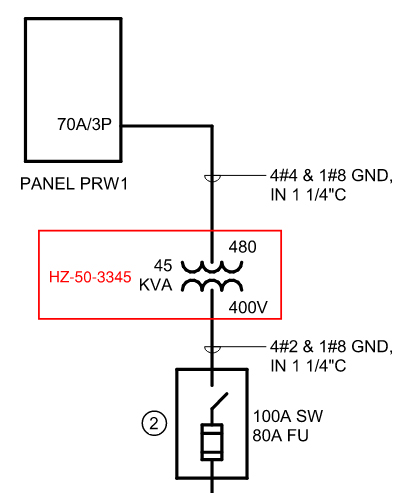
Our current electrical connections are as follows:
We are feeding the frequency converter with 480V from a 70A, 3 Pole, Breaker.
We ran (4) #4awg cables from this panel to the frequency converter unit
We are then feeding out of the frequency converter (load side) to a 100A Rated, 3Pole, 600V, 3W, disconnect that has 80A trip, 600V rated, Type RK5 fuses (FRS-R-80).
We ran (4) #2awg cables from the frequency converter to the disconnect.
The load side of the disconnect feeds process equipment that needs 380V @ 50Hz to run.
The issue we are currently experiencing is:
During the startup/testing of the process equipment fed by this converter, it will intermittently cause the frequency converter to trip and go into alarm mode. This does not occur every time, however, it has occurred multiple times and keeps occurring.
The sequence of events that we have found to most likely cause the trip has been:
The process equipment has a safety function that, when a sensor is set off, it will put the process equipment itself into an ‘Emergency Stop’ mode, shutting down all the motors, pumps, etc. for safety. Upon this “Emergency Stop” function, the frequency converter goes into alarm and shuts down all output power. Once we reset the converter and turn the output back on, things work as normal; Until the next time the safety sensor goes into ‘emergency stop’ mode and it repeats the above issue with the converter going into alarm and killing output power.
We do not see a spike in current on the converter’s LCD output readings, at any time, during the testing of the process equipment.
The highest amperage level we have read at any time was less than 5A.
This includes readings on all output current Phase Switch Positions. (U-V, V-W, W-U)
Is there a setting in the frequency converter that will cause an alarmed trip during a rapid shutdown of a load draw on the Unit? Do you have any suggestions on tests we can perform to ensure the HZ-50-3345 is operating properly?
The HZ-50-3345 frequency converter output is set at 380V Line-Line @ 50Hz.
Our current electrical connections are as follows:
We are feeding the frequency converter with 480V from a 70A, 3 Pole, Breaker.
We ran (4) #4awg cables from this panel to the frequency converter unit
We are then feeding out of the frequency converter (load side) to a 100A Rated, 3Pole, 600V, 3W, disconnect that has 80A trip, 600V rated, Type RK5 fuses (FRS-R-80).
We ran (4) #2awg cables from the frequency converter to the disconnect.
The load side of the disconnect feeds process equipment that needs 380V @ 50Hz to run.
The issue we are currently experiencing is:
During the startup/testing of the process equipment fed by this converter, it will intermittently cause the frequency converter to trip and go into alarm mode. This does not occur every time, however, it has occurred multiple times and keeps occurring.
The sequence of events that we have found to most likely cause the trip has been:
The process equipment has a safety function that, when a sensor is set off, it will put the process equipment itself into an ‘Emergency Stop’ mode, shutting down all the motors, pumps, etc. for safety. Upon this “Emergency Stop” function, the frequency converter goes into alarm and shuts down all output power. Once we reset the converter and turn the output back on, things work as normal; Until the next time the safety sensor goes into ‘emergency stop’ mode and it repeats the above issue with the converter going into alarm and killing output power.
We do not see a spike in current on the converter’s LCD output readings, at any time, during the testing of the process equipment.
The highest amperage level we have read at any time was less than 5A.
This includes readings on all output current Phase Switch Positions. (U-V, V-W, W-U)
Is there a setting in the frequency converter that will cause an alarmed trip during a rapid shutdown of a load draw on the Unit? Do you have any suggestions on tests we can perform to ensure the HZ-50-3345 is operating properly?
0
