Close
(0) Shopping cart
You have no items in your shopping cart.
Shopping Categories
    Filters
    Preferences
    Search
    Saturday, January 4, 2025 12:22:19 AM

    How to Set Up 3hp Single Phase VFD to Run an Exhaust Fan?

    2 months ago
    #230 Quote
    Hello, everyone! I have an ATO single phase VFD GK3000-1S0022, 3hp (2.2 kW), I would appreciate it if you help me:
    1. To set up this VFD to run a single phase motor of an Exhaust Fan. Motor has a capacitor. Input and output power is single phase 208-230V.
    2. There is also a contactor in the power line to start and stop the Fan. The CO control system calls on and off the contactor to control the CO in the parking. I wonder if I should install the contactor between the power source and VFD or between the VFD and Load (Exhaust Fan).
    1
    2 months ago
    #231 Quote
    Esmaeil wrote:
    Hello, everyone! I have an ATO single phase VFD GK3000-1S0022, 3hp (2.2 kW), I would appreciate it if you help me:
    1. To set up this VFD to run a single phase motor of an Exhaust Fan. Motor has a capacitor. Input and output power is single phase 208-230V.
    2. There is also a contactor in the power line to start and stop the Fan. The CO control system calls on and off the contactor to control the CO in the parking. I wonder if I should install the contactor between the power source and VFD or between the VFD and Load (Exhaust Fan).

    Hi Esmaeil,
    1. The 2 power lines of your single-phase motor can be directly connected to the U, W, or U, V terminals of the VFD output terminals.
    2. We recommend using a circuit breaker installed between the power supply and the single phase VFD, without installing a contactor between the VFD and the load (exhaust fan), then you can just use the CO control system to call the trigger signal for controlling the VFD's start/stop signal. For example, your CO control system can trigger a relay, and then you can indirectly control the on/off of the VFD through the NO contact of the relay.
    1
    ATO.com
    2 months ago
    #232 Quote
    ATO wrote:
    Hi Esmaeil,
    1. The 2 power lines of your single-phase motor can be directly connected to the U, W, or U, V terminals of the VFD output terminals.
    2. We recommend using a circuit breaker installed between the power supply and the single phase VFD, without installing a contactor between the VFD and the load (exhaust fan), then you can just use the CO control system to call the trigger signal for controlling the VFD's start/stop signal. For example, your CO control system can trigger a relay, and then you can indirectly control the on/off of the VFD through the NO contact of the relay.

    Thank you for your prompt response.
    1. Please let me know how to set up the VFD menus.
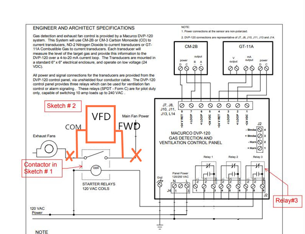
    2. Please see the attached two sketches.
    Sketch#1 shows how we wired the VFD and other components.
    Sketch#2 shows the controller and how to control the load contactor.
    The relay#3 inside the controller in sketch 2 triggers the contactor in the sketch1.

    0
    2 months ago
    #233 Quote
    Esmaeil wrote:
    Thank you for your prompt response.
    1. Please let me know how to set up the VFD menus.
    2. Please see the attached two sketches.
    Sketch#1 shows how we wired the VFD and other components.
    Sketch#2 shows the controller and how to control the load contactor.
    The relay#3 inside the controller in sketch 2 triggers the contactor in the sketch1.


    1. For menu programming of VFD, you can refer to our demo video at https://www.youtube.com/watch?v=zxTVneMG5Jo&list=PLlo8RulDRnthBFbP4ydheukDSKw2hAfDn&index=27
    2. For sketch #1, the contactor between the VFD and the fan should be removed and the fan should be connected directly to the VFD.
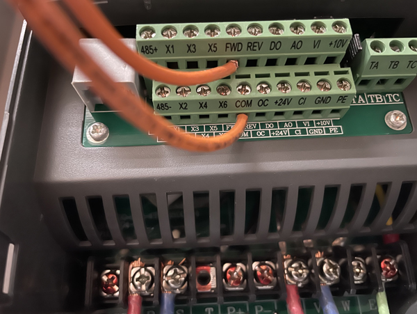
    For sketch 2, you can keep relay #3 triggering the contactor (in sketch 1), and then use the contact (NO) in sketch 1 to control the VFD control terminal FWD-COM for the purpose, thus indirectly controlling the start and stop of the VFD. Please refer to the attached wiring.
    0
    ATO.com
    2 months ago
    #234 Quote
    ATO wrote:
    1. For menu programming of VFD, you can refer to our demo video at https://www.youtube.com/watch?v=zxTVneMG5Jo&list=PLlo8RulDRnthBFbP4ydheukDSKw2hAfDn&index=27
    2. For sketch #1, the contactor between the VFD and the fan should be removed and the fan should be connected directly to the VFD.
    For sketch 2, you can keep relay #3 triggering the contactor (in sketch 1), and then use the contact (NO) in sketch 1 to control the VFD control terminal FWD-COM for the purpose, thus indirectly controlling the start and stop of the VFD. Please refer to the attached wiring.

    I remove the contactor from the power line between the VFD and the fan.
    When I push the FWD button on the panel, the fan starts to work almost 6 minutes and turns off automatically. Fan will be turned off if I push the STOP button on the panel before 6 minutes.
    I connect the FWD and COM connections to each other in the VFD. Nothing happened. I disconnected them again and nothing happened.
    When the fan does not turn on or off with tying and untying the FWD-COM points, I wonder how I can turn on and off the Fan using the VFD and contactor.
    0
    2 months ago
    #235 Quote
    Esmaeil wrote:
    I remove the contactor from the power line between the VFD and the fan.
    When I push the FWD button on the panel, the fan starts to work almost 6 minutes and turns off automatically. Fan will be turned off if I push the STOP button on the panel before 6 minutes.
    I connect the FWD and COM connections to each other in the VFD. Nothing happened. I disconnected them again and nothing happened.
    When the fan does not turn on or off with tying and untying the FWD-COM points, I wonder how I can turn on and off the Fan using the VFD and contactor.

    If you would like to use FWD and terminal COM to control the VFD, you should set the following parameters:
    P0.03=1 (run the command from terminal)
    P4.08=0 (2-wire control mode 1)
    0
    ATO.com