Current transformer consists of closed iron core and winding. It has few primary winding that are connected in series in the current circuit under measurement; however, it has many secondary winding, which are connected in series in the measuring instrument and protection circuits. The current transformer plays the role of converter and electrical isolation, it's a sensor for measuring instrument, relay protection and other secondary equipment to obtain current information of primary circuit in power system. It converts the high current to a low current by ratio, its primary end is connected with the primary system, while the secondary end is connected with the measuring instrument and relay protection.
Tag: working principle
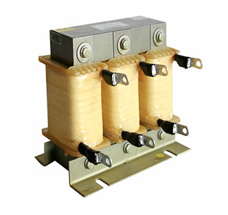
A conductor will produce magnetic field in a certain range of space it occupies when it's powered on, so all electric conductors carrying current are inductive on a general sense. However, a long straight conductor often generates a small inductance, the generated magnetic field is not strong, so the actual line reactor is a wire wound solenoid, which is also called air core line reactor. Sometimes an iron core would be inserted into the solenoid to generate greater inductance, which is called iron core line reactor. Reactance is divided into inductive reactance and capacitive reactance, in the more scientific division, both impedor (inductor) and reactance (capacitor) are called line reactor. However, as inductor appeared earlier and was called line reactor, the capacitor people often say only refers to the reactance, and line reactor refers specifically to the inductor. Main function of three-phase output line reactor is to compensate the influence of long line distributed capacitance, restrict the output of harmonic current and improve output high frequency impedance, thus protecting the inverter.
UPS power system consists of 4 parts: rectification, energy storage, transformation and on-off control. UPS realizes the function of voltage stabilization with rectifier, which is generally a silicon-controlled rectifier (SCR) or high-frequency switching rectifier. The rectifier controls the output amplitude according to the change of external power supply; when the external power supply changes (the change should meet the system requirements), it outputs a rectified voltage whose amplitude keeps unchanged. Purification function of UPS is completed by the energy storage battery. As the rectifier cannot eliminate instantaneous pulse interference, the rectified voltage still has interference pulse. Energy storage battery can not only store DC power, but also plays a role of large-capacity capacitor for the rectifier, its equivalent capacitance is proportional to the capacity of energy storage battery. As the voltage at both ends of the capacitor can’t change suddenly, the pulse interference is eliminated due to the smoothness property of capacitor for pulses, thus realizing the purification, as well as the shielding against interference. Converter guarantees a stable frequency of uninterruptible power supply. Frequency stability is determined by the stability of the converter's oscillation frequency. To facilitate daily operation and maintenance of UPS power system, an operating switch, automatic bypass switch after fault self-checking, overhaul bypass switch are designed in this system.
A built-in power lightning protection device should be used in the internal power supply of the electrical equipment which functions as the final line of defense, so as to completely eliminate the tiny transient overvoltage. The power lightning arrester used at this level requires a maximum impact capacity of 20KA per phase or less, and the required limit voltage should be less than 1000V. It is necessary to provide class-III protection for some particularly important or sensitive electronic devices, as well as to protect the electrical equipment from transient overvoltage produced within the system.
Brushless DC motor (BLDC) uses electronic phase-changing circuit to supply DC power to motor rotor winding. Since there is no mechanical brush, it is called brushless DC motor. Because of brushless DC motor with high efficiency and accurate control performance, and can use the electronic packaging to meet the needs of security specification features. Under the demands of global energy conservation and carbon reduction, it is widely applied in the field of air conditioning, such as common DC inverter, brushless DC technology; it also can be used in hybrid electric vehicle and some appliances of high economic value, such as electric fans and other products.
Safety relay can be classified into electromagnetic safety relay, thermal reed relay and solid-state relay. The working principle of safety relays can also be roughly divided into three types. Safety relay is composed of several relays and circuits, so as to supplement each other's abnormal defects and achieve the complete function of relay with correct and low faulty operation, so as to make the error and failure value become lower, thus reaching higher safety factor. Therefore, multiple safety relays should be designed to protect different grades of machinery. It is used to mainly protect the mechanical operators who perform operation under different levels of risk.
How does a transformer work? Transformers mainly applies electromagnetic induction principle to work, the working principle details are as follows: When the primary side of the transformer is applied with the alternating voltage U1 and the current flowing through the primary winding is I1, then the current will generate alternating magnetic flux in the iron core to generate electromagnetic connections between the primary winding and the secondary windings.
Brushless DC motor consists of the motor and drive, is a typical mechatronic product. The stator windings of the motor are mostly made using three-phase symmetrical star connection, which is very similar to the three-phase asynchronous motor. Magnetically charged permanent magnets are attached to the rotor of the motor. In order to detect the polarity of the motor rotor, a position sensor is provided in the motor.
The solenoid valve is industrial equipment controlled by electromagnetism. It is an automatic basic element to control the fluid. It belongs to the actuator, but not limits to the hydraulic pressure and pneumatic control. In the industrial control system, the solenoid valve is used to regulate the direction, flow rate, speed and other parameters of the medium. The solenoid valve can coordinate with different circuits to realize the anticipated control, with both control precision and flexibility being guaranteed.
How does an 3-phase induction motor work? In short, it works based on the principle of electromagnetic induction. When the stator windings are supplied with three-phase alternating current, a rotating magnetic field is generated between the stator and the rotor. The rotating magnetic field cuts the rotor windings to generate induced electromotive force and current in the rotor circuit. The current in the rotor conductor forces the rotor to rotate under the effect of the rotating magnetic field. Below, let’s specifically analyze the generation of rotating magnetic field, its direction and speed as well as slip.
Magnetostrictive sensor indicates a kind of displacement detecting device developed based on ferromagnetic material magnetostrictive effect. It could be used for continuously, precisely and real-time detecting the displacement (position) and velocity of various moving parts under abominably industrial environment. As an important component to realize precise operation and control, it can substantially enhance the precision and efficiency of the whole system. It is applicable for detecting the stroke or position of mechanical device with rectilinear motion. Precision servo feedback control of hydraulic system is one of the most typical applications.
How does an electromagnetic relay work? Electromagnetic relay uses electromagnet to control “on” or “off” status of the operating circuit. Electromagnetic relay consists of electromagnet, armature, spring, movable contact and stationary contact. When placing voltage to both ends of a coil, the coil will be flowed with current and generate electromagnetic effect.
The planetary speed reducer or gearbox is a kind of transmission mechanism. It utilizes the speed transducer of the gearbox to reduce the turnover number of the motor to the required one and obtain a big torque. How does a planetary gearbox work? We can learn more about it from the structure. The main transmission structure of the planetary gearbox is planet gears, sun gear and ring gear.
What is a power line filter? What does a power line filter do? A power line filter, also called EMI power line filter, is a passive bi-directional network, electrical equipment which effectively filters the particular frequency point in the power line or the frequency out of the particular frequency point. Power line filter is to get a certain frequency power supply signal or the power supply signal after eliminating a certain frequency through connecting power supply filter in power line...
What is a solid state relay(SSR)? A solid state relay is a non-contact switch fully composed of solid state electrical-element, which can drive high-current load with a small control signal. It can achieve switching on and off with no contact and no spark due to the switching characteristics of electrical element (i.e. semiconductor components like switch transistor, triac and so on). Solid state relay has such following advantages over electromagnetic relays: high reliability, no contact, no spark, long life, fast switching speed, strong anti-interference ability, and small size.
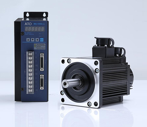
What is a servo motor? Servo motor is the motor which controls mechanical components operation in servo system. Servo motor can convert voltage signal to torque and speed, then to drive the control object. The control speed and position accuracy is very high. In auto control system, servo motor can response rapidly as executing component, convert the receiving electrical signal to angular displacement or angular velocity output of motor axis. The main feature is, when signal voltage is zero and no self-rotation, rotation speed will descend at even speed along with the torque increasing. Servo motor has 2 types, DC servo motor and AC servo motor.
The servo drive is a kind of controller to control the servo system. Its function is similar to the frequency effect on ordinary AC motor, which belongs to a part of the servo system and is mainly applied in high-accuracy positioning system. Generally, the servo motor is controlled by three ways, location, speed and torque, so as to realize high precision positioning of transmission system.
Stepper motor is an actuator transforming electric pulse into angular displacement. Popularly, when receiving a pulse signal, the stepper motor will rotate a fixed angle (namely"stepping angle") according to the direction set for the stepper motor. The angular displacement volume can be controlled by controlling the pulse number to achieve the purpose of positioning accurately. In the meantime, the rotational velocity and acceleration of motor can be controlled by controlling the pulse frequency to achieve the purpose of speed control.

