BLDC Motor
The brushless DC motor (BLDC motor) is actually a three-phase synchronous motor: The rotor follows a rotating magnetic field, and its motion synchronizes with the AC voltage applied to the winding. Usually in the brushed DC motor, after applying DC voltage, the mechanical inverter (brush) in the motor will generate AC power independent of the speed. Different from the brushed DC motor, brushless DC motor cooperates with the electronic drive controller to replace the function of the brush and convert the fed DC power into AC power, which achieve the performance equivalent to the brushed DC motor without the brush with limited service life. Therefore, BLDC motors are also called EC (electronic commutation) motors to distinguish them from mechanical commutation motors that include brushes. In many applications, Brushless DC motor is a perfect solution to replace a brushed DC motor or a commutator motor.
Contents
- Brushless DC Motor Structure
- Brushless DC Motor Working Principle
- Pole Pairs of 3-Phase Brushless DC Motor
- Difference between Brushed DC Motor and Brushless DC Motor
- Why Buy Brushless DC motors on ATO.com Online Store?
- Brushless DC Motor and Controller Wring
- Brshless DC Motor Control
- Brushless DC motor Application
Brushless DC Motor Structure
Most brushless DC motors are inrunner motors, whose stator is fixed with coils, and the rotor in the middle rotates under the action of permanent magnets on the rotating shaft. In the outrunner motor the stator is located inside, and the rotor consists of a bell shaped housing that rotates outside, on which the magnet is mounted. Both the inner and outer rotor motor use slot windings, and the winding wire is wound on the iron core, so that the magnetic field lines of the winding can flow out and converge into a certain shape. In order to minimize the eddy current loss, the stator is made of thin insulating metal plates that cancel each other out.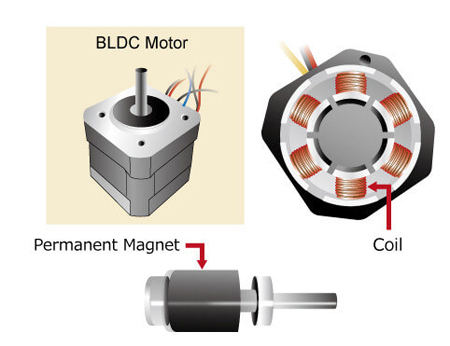
The advantage of the inrunner BLDC motor is that the rotor has a low rotational inertia and fast heat dissipation. On the contrary, in the outrunner BLDC motor, due to the presence of the rotor casing and the magnet, the heating coil is isolated from the environment, and the heat dissipation is relatively slow. Because the rotor's moment of inertia is large and it is difficult to control the balance of the rotor housing, the outer rotor motor is not suitable for the mode with a high rotation speed. Therefore, internal rotor motors are widely used in most industrial applications and are usually designed as three-phase high torque BLDC motor or small high speed BLDC motor.
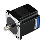
The figure on the right shows the appearance and internal structure of a typical inner rotor type brushless DC motor. It should be noted that the permanent magnet of this motor is installed on the rotor, while the coil is located on the outside. This is completely different from brushed DC motors with coils on the rotor and permanent magnets on the outside. Since the rotor of the BLDC motor does not use the coil, there is no need to supply current to it, which is why there is no carbon brush.
Brushless DC Motor Working Principle
It is known that the stator of BLDC motor is the coil winding armature, and the rotor is the permanent magnet. If fixed DC current is applied to the BLDC motor, the motor only generate a constant magnetic field and cannot rotate. Only when the position of the motor rotor is detected in real time, and then the corresponding current is applied to the motor phase according to the position of the rotor, so that the stator produces a rotating magnetic field with uniform direction change, then the motor can rotate with the magnetic field.
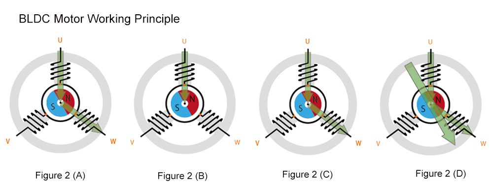
Figure 2 (A): Three coils spaced 120-degree by controlling phase and coil current.
Figure 2 (B): The current passes through U first and then through W. The arrow shows the magnetic flux produced by the coil U.
Figure 2 (C): The current flows through U and W. The two arrows represent the magnetic flux generated by the coil U and W respectively.
Figure 2 (D): The broad arrow represents the resultant magnetic flux—the sum of the magnetic fluxes produced by U and W.
Figure 2 (A) shows the stator (coil) and rotor (permanent magnet) of a three-phase brushless DC motor with three coils. We will take this diagram to illustrate how to rotate the rotor. To make the brushless DC motor work, we need to know the direction and timing of the current into the coil. In this example, three coils spaced 120º are labeled U, V, W respectively. When the current passes through these three coils, three corresponding magnetic fields are generated, which are called U-phase, V-phase and W-phase. If the current only passes through the U phase, the resulting magnetic flux is shown by the arrow in Figure 2 (B). In fact, all three coils are connected by a wire from each coil, and it is impossible to generate the U phase alone. Figure 2 (C) shows the current passing through the U and W coils, and the magnetic flux generated by each coil is also indicated by the arrow. The wide arrow in Figure 2 (D) is the synthetic flux, which is the result of combining the magnetic fields of U and W. This large flux will cause the internal rotor to rotate until the S and N poles of the rotor permanent magnet are aligned with this arrow (the N pole is closest to the tip of the arrow). In short, U, V and W must be switched on continuously to keep the synthetic flux moving, so as to generate a rotating magnetic field that continuously affects the rotor magnet and keeps the motor working.
Read the related blog: Brushless DC Motor, How it works?
Pole Pairs of 3-Phase Brushless DC Motor
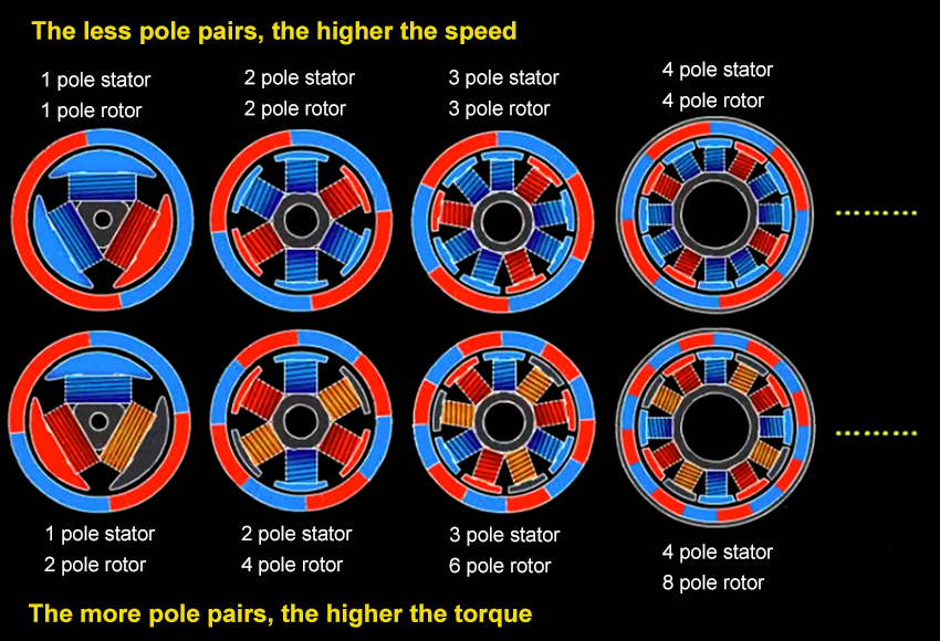
Each coil of three-phase synchronous motor will produce N and S poles, and the number of magnetic poles in each phase is the poles number of the motor. Since the magnetic poles appear in pairs, the brushless DC motor has 2, 4, 6, 8... poles.
When the windings of each phase of A, B, C phase have only one coil evenly and symmetrically distributed on the circumference, the current changes once and the rotating magnetic field rotates one circle, which is a pair of poles. If the three-phase windings of A, B, C are composed of two coils in series, and the span of each coil is 1/4 circle, then the composite magnetic field created by the three-phase current is still a rotating magnetic field, and the current changes once, the rotating magnetic field only rotates 1/2 turn, which is 2 pairs of poles. Similarly, if the windings are arranged according to certain rules, 3 pairs of poles and 4 pairs of poles can be obtained.
The eight pole motor has eight magnetic poles, that is, the motor has four pairs of magnetic poles. In the case of constant output power, the more pole pairs of the motor, the lower the motor speed, but the greater the torque. Therefore, when selecting the motor, consider how much starting torque the load needs.
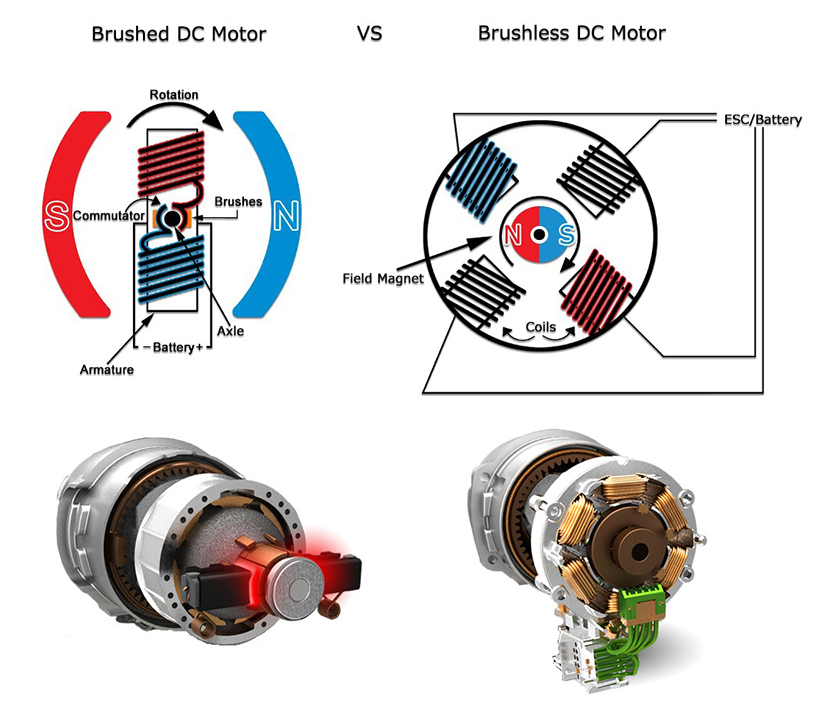
Difference between Brushed DC Motor and Brushless DC Motor
Brushed DC Motor
- When the brushed DC motor works, the winding coil and commutator rotate, the permanent magnet and carbon brush do not rotate, and the alternating change of coil current direction is completed with the motor rotating commutator and brush. It relies on the phase change of the carbon brush and the rotor to change the magnetic pole of the winding coil, so when the phase is changed suddenly, a spark will be generated. The friction time between the carbon brush and the rotor will consume the carbon brush and affect the service life of the motor.
- Brushed DC motor is cheap price and easy to control, only need to adjust the current at the rated voltage to control the speed. However, brushed DC motor has small starting torque, and it is easy to get stuck in the case of large friction. Therefore, brushed DC motors are only suitable for occasions where the motor requirements are not high.
- During the maintenance of brushed DC motor, not only the brush but also other accessories such as swivel gear should be replaced, which will increase the cost and affect the performance of the whole machine. Moreover, the brushed DC motor has such disadvantages: Large size, small power, short life and carbon brushes are easily overloaded at long periods of work.
Brushless DC Motor
- The brushless DC motor adopts electronic commutation, the coil does not move, and the magnetic pole rotates. The Hall element senses the position of the magnetic pole of the permanent magnet. Based on this perception, an electronic circuit is used to switch the direction of the coil current in time to ensure that the magnetic force in the correct direction is generated to drive the motor, eliminating the disadvantages of the brushed DC motor.
- Low speed and high power operation. The most outstanding feature of brushless DC motors over ordinary motors is that they can operate normally at lower speeds and with greater power. Because the brushless DC motor has the advantages of the traditional DC motor, and at the same time eliminates the carbon brush and slip ring structure, the machine can run at low speed and high power, and can save the speed reducer to directly drive a large load. Because the motor itself does not have carbon brushes and excitation consumption, it eliminates multi-stage deceleration energy consumption. BLDC motor can also realize stepless speed regulation, and its speed regulation range is very wide, and its overload capacity is also stronger.
- Simple repair and maintenance. It is one of the outstanding characteristics of the brushless DC motor. Due to the small size and light weight of the BLDC motor, the maintenance is relatively simple. At ordinary times, the operators can prevent various faults of the motor through daily maintenance, and effectively extend the life of the machine.
Read the related blog: Brushed DC Motor vs. Brushless DC Motor.
Why Buy Brushless DC motors on ATO.com Online Store?
ATO offers a wide range of best brushless dc electric motors and controllers deliver high torque, efficiency and speed in small dimensions to meet your specific requirements. The unique design of our BLDC motor kits allows for several key benefits as follow and they are widely use in new energy electric car, medical, automation, packaging and so on.
For ATO BLDC Motor
- Customized 3 phase 8 pole (4 pair of poles) brushless DC electric motor with rating power from 100W to 15kW
- Come with different compact square flange size of 60mm, 80mm, 110mm, 130mm, 180mm
- High torque BLDC motor working at 12V/ 24V/ 48V DC voltage power supply, 72V/ 96V is also available
- High speed 5000rpm to 17000rpm small brushless DC motor with 12 volt / 24 volt
- 1000 rpm to 3000 rpm rated speed, IP65 for protection, high efficiency up to 85%
- Strong starting torque, high power density, small moment of inertia, low noise
- Offers competitive added value options such as along with brake, the matched bldc motor controller, fitting it to a planetary / worm gearbox for increased torque
For ATO BLDC Motor Controller
- Specially designed for electric vehicles like electric motorcycles and scooters
- Support any pole number of high power and high torque brushless DC motor
- Anti-electromagnetic interference, strong anti-vibration performance
- Fault indicator indicates various faults, which is convenient for users to detect and maintain
- Powerful and intelligent microprocessors, high-speed low-loss synchronous rectification PWM modulation
- Greater starting current can get a faster start-up speed, providing smooth, efficient operation at various speed ranges
- With over-temperature protection function: When the temperature is too high or too low, the current will be automatically attenuated to protect the controller and battery
BLDC motor must be worked together with the controller. Why? The main reason is that: Brushless DC motor has no brush and commutator, there must be an electronic commutator to maintain the direction of rotation. The electronic commutator is composed of six power MOSFET transistors, which are controlled by a brushless motor controller. At the same time, the controller can also control the starting and stopping of the motor, forward and backward, speed regulation, over-voltage, over-current and under-voltage protection. So it is necessary to have a brushless motor controller, even if the brushless DC motor is directly powered on, it is useless.
In general, BLDC motor combines with the BLDC controller and gearbox are cost-effective solutions for motion control applications where high efficiency and high torque are required. ATO will recommend several top selling brushless DC motors and their matching BLDC controllers to meet your needs in the table below. If you need the information and quotations for all motor models, please go to our product catalog manual and price list.
| Product | SKU | Price | Rated Power | Rated Voltage | Rated Speed | Rated Torque | Matched Controller |
 |
ATO-BLDC-200R3 | $245.39 | 200W | 24V/48V DC | 3000rpm | 0.64Nm | ATO-BLD-750 |
 |
ATO-BLDC-1000R3 | $415.85 | 1000W | 24V/36V/48V DC | 3000rpm | 3.18NM | ATO-BLD-50 |
 |
ATO-BLDC-1500R3 | $432.36 | 1.5kW | 36V/48V DC | 3000rpm | 4.78Nm | ATO-BLD-100 |
 |
ATO-BLDC-750R3 | $352.77 | 750W | 24V/48V/72V/96V DC | 3000rpm | 2.4Nm | ATO-BLDC-TH-G |
 |
ATO-BLDC-2000R2 | $816.24 | 2kW | 48V/72V/96V DC | 2000rpm | 10Hm | |
 |
ATO-BLDC-3000R3 | $879.12 | 3kW | 48V/72V/97V DC | 3000rpm | 10Nm | |
 |
ATO-BLDC-5000R3 | $1,746.93 | 5kW | 48V/72V/98V DC | 3000rpm | 16Nm |
Brushless DC Motor and Controller Wring
The brushless DC motor with 60-degree and 120-degree phase angle needs to be driven by corresponding brushless controller with 60-degree and 120-degree phase angle, and the controllers of two phase angles cannot be directly exchanged. There are two kinds of correct wiring for the 8 wires connecting the brushless motor with 60 degree phase angle to the controller with 60 degree phase angle, one is forward rotation and the other is reverse rotation. For a brushless motor with a phase angle of 120 degrees, by adjusting the phase sequence of coil leads and hall leads, there are six correct wires connected to the motor and controller, three of which are connected to the motor for forward rotation and the other three to the motor for reverse rotation. If the brushless motor reverses, indicating that the phase angle of the brushless controller and the brushless motor match, the direction of the motor can be adjusted by changing the A and C wiring between the hall lead of the brushless motor and the brushless controller. At the same time, the main phase lines A and B of the brushless DC motor and the brushless controller are switched.
Generally, most of brushless DC motor with controller wiring is basically similar in the principle. ATO high torque BLDC electric motor is equipped with three power extension wires and five Hall signal wires. These 8 wires must correspond to the corresponding leads of the controller one by one, otherwise the motor cannot rotate normally. We will take ATO 400W 24 volt BLDC motor and its matching controller as examples to show you how to connect the motor to the controller and make the motor rotate. Watch the video below for more detailed of BLDC motor with controller wiring instructions. The wiring operation is also suitable for ATO all high torque 24V/ 48V/ 72V/ 96V brushless DC motor.
Brushless DC Motor Control
PWM Speed Control of BLDC Motor
The basic principle of PWM control speed: Control the on and off of the switching devices of the inverter circuit, so that a series of pulses of equal amplitude are obtained at the output end, and these pulses are used to replace the sine wave or the required waveform. That is, multiple pulses are generated in the half cycle of the output waveform, so that the equivalent voltage of each pulse is a sinusoidal waveform, and the output is smooth and low-order harmonics are few. Modulating the width of each pulse according to certain rules can change the output voltage of the inverter circuit and the output frequency.
The PWM speed control principle of the DC brushless motor is different from the AC motor speed control principle. It does not adjust the speed of the motor through frequency modulation, but changes the amplitude of the voltage delivered to the armature by adjusting the pulse width of the driving voltage, so as to achieve the purpose of changing the speed of the brushless DC motor. Its modulation method is amplitude modulation. And there are two ways of PWM speed control:
- PWM signal is used to control the conducting time of the audion. The longer the conducting time is, the longer the working time is, the higher the speed of the motor will be.
- Use PWM control signal to control the triode conduction time and change the control voltage.
Forward and Reverse Control of BLDC Motor
By changing the logic relationship of the switch tubes of the inverter, the turn-on sequence of each phase of the armature winding is changed to realize the forward and reverse rotation of the motor. In order to produce the maximum average electromagnetic torque in both forward and reverse rotations of the motor to ensure symmetrical operation, the mutual positional relationship between the rotor position sensor and the main magnetic pole of the rotor and each phase winding of the stator must be designed, as well as the correct logical relationship.
Forward/reverse control (DIR)
The running direction of the motor can be controlled by controlling the on and off of terminal "DIR" and terminal "COM". The terminal "DIR" is pulled up to +12 with a resistance inside, which can be used with passive contact switches, or with control units such as PLC with open collector. When "DIR" and terminal "COM" are not connected, the motor runs clockwise (facing the motor shaft), otherwise, it runs counterclockwise. in order to avoid damage to the brushless DC controller, the BLDC motor should be stopped before changing the motor direction.
Speed signal output (SPEED)
The brushless DC controller provides users with a pulse signal proportional to the motor speed through the terminals SPEED~COM. Number of pulses per revolution equals 6 times number of motor pole pairs, SPEED frequency (Hz) equals number of pulses per revolution multiplied by speed (rev/min) divided by 60. Example: 4-pole motor, 24 pulses per revolution, when the motor speed is 500 revolutions per minute, the output frequency of terminal SPEED is 200 Hz.
Read the related blog: Control Methods of BLDC Motor.
Brushless DC motor Application
- Continuous load application: It mainly refers to the field that requires a certain speed but does not require high speed accuracy, such as fan, water pump, air blower and other applications, which are low cost and mostly open-loop control.
- Variable load application: It is mainly the application that the speed needs to change in a certain range, which has higher requirements for the motor speed characteristics and dynamic response time characteristics. Such as household appliances, dryer and air compressor are good examples, the automotive industry in the field of oil pump control, electrical controller, engine control, such as the system cost is relatively higher.
- Positioning application: Most industrial control and automatic control applications belong to this category. In this kind of application, energy transmission is often completed, so there are special requirements for dynamic response and torque of rotating speed, and higher requirements for controller. Photoelectric and some synchronous devices may be used for speed measurement. Process control, mechanical control and transportation control are many of these applications.
