Stepper Motors
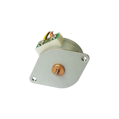
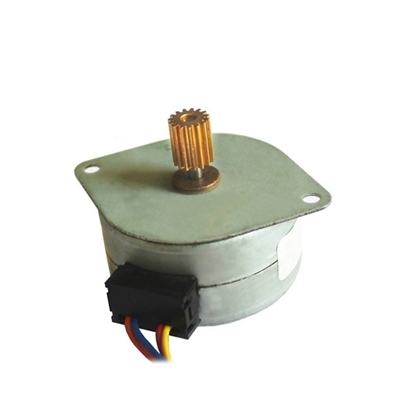
Nema 10 Micro Stepper Motor, 6V/ 24V, 15 Degree, Bipolar
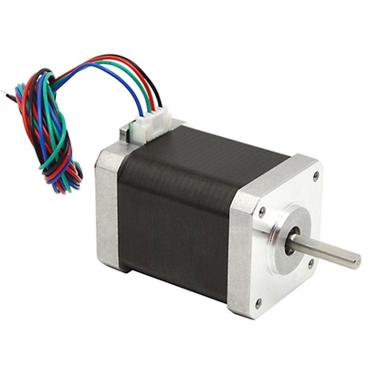
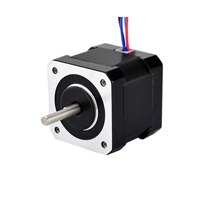
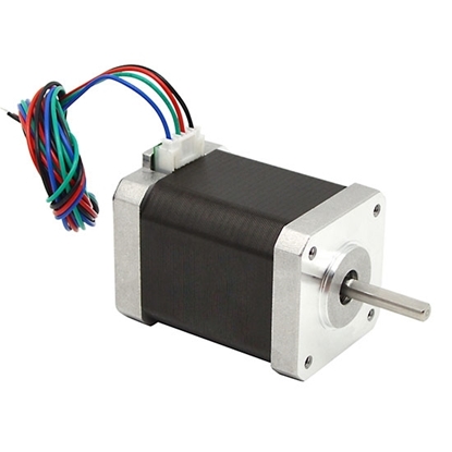
Nema 17 Stepper Motor, 2 Phase, 1.8A, 0.5N·m
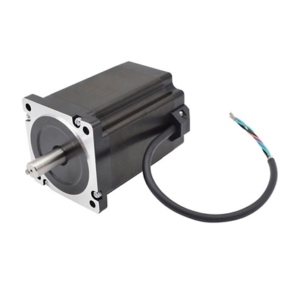
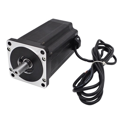
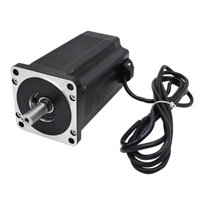
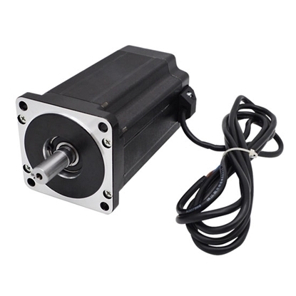
Nema 34 Stepper Motor, 2 Phase, 5A, 12N·m
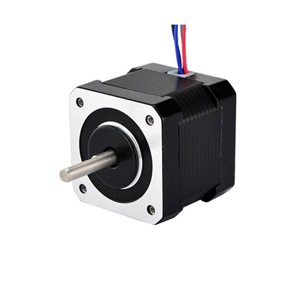
4-wire Nema 17 Bipolar Stepper motor, 6V 0.8A, 1.8 degree
Nema 14 Micro Stepper Motor, 12V, 4 Phase, Bipolar
Nema 17 Bipolar Stepper motor, 2.8V 1.68A, 2 phase 4 wires
Nema 17 Stepper Motor, 2 Phase, 2A, 0.65N·m
Nema 34 Stepper Motor, 3 Phase, 2A, 4N·m
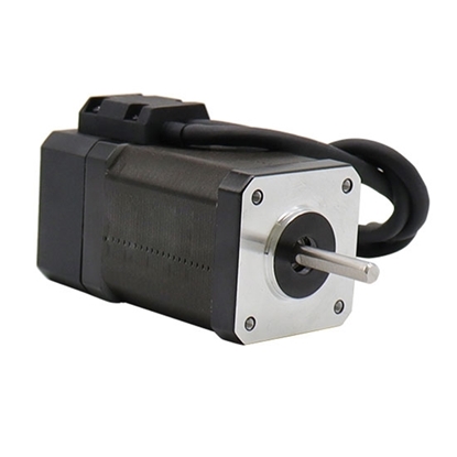
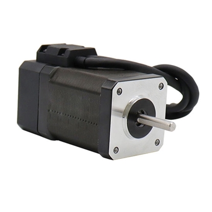
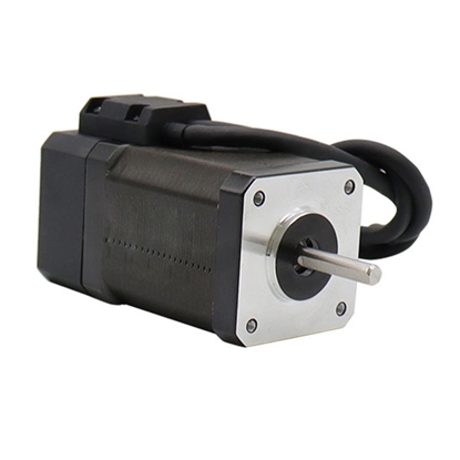
Nema 17 Closed Loop Stepper Motor, 2 Phase, 2A, 0.4N·m
Nema 17 Micro Stepper Motor, 12V/ 24V, 7.5 Degree
Nema 34 Stepper Motor, 3 Phase, 3A, 6N·m
Nema 17 Closed Loop Stepper Motor, 2 Phase, 2A, 0.5N·m
Nema 34 Stepper motor, 3 Phase, 3.2A, 8.5N·m
Nema 17 Closed Loop Stepper Motor, 2 Phase, 2A, 0.72N·m
2-phase Nema 34 Stepper motor, 1.8 degree, 4.5A, 4 wires
2-phase Nema 34 Stepper motor, 4A, 1.8 degree 4 wires
4-wire Nema 34 Stepper motor, 3A, 1.8 degree, 2 phase
CNC Nema 34 Stepper motor, 1.8 degree, 6A, 4 wires 2 phase
High Torque Nema 34 Stepper motor, 8A, 1.8 degree, 4 wires
Nema 34 2 phase Stepper motor, 1.8 degree, 6A, 4 wires
Stepper motor is an open loop or closed loop control motor that divides a full rotation into a number of equal steps. The motor's position can be controlled to move and hold at one of these equal steps. Stepper motors come in many different sizes and styles, and they are widely used in a variety of automated control systems.
ATO sells different series of stepper motors, including Nema 17 stepper motor, Nema 23 stepper motor, Nema 24 stepper motor, Nema 34 stepper motor, Nema 42 stepper motor, micro stepper motor and linear stepper motor. We also offer you the best price with high quality and service. All the stepper motors are direct sell by manufacturer, now you can view the lists and start ordering.
How does a stepper motor work?
The stepper motor rotor is a permanent magnet, when the current flows through the stator winding, the stator winding to produce a vector magnetic field. The magnetic field drives the rotor to rotate by an angle so that the pair of magnetic fields of the rotor and the magnetic field direction of the stator are consistent. When the stator's vector magnetic field is rotated by an angle, the rotor also rotates with the magnetic field at an angle. Each time an electrical pulse is input, the motor rotates one degree further. The angular displacement it outputs is proportional to the number of pulses input and the speed is proportional to the pulse frequency. Change the order of winding power, the motor will reverse. Therefore, it can control the rotation of the stepping motor by controlling the number of pulses, the frequency and the electrical sequence of each phase winding of the motor.
Advantages of stepper motors
- Precise position control, as confirm the shaft rotation angle in accordance with the number of input pulses.
- Wide speed range, because the speed is proportional to the pulse frequency.
- Excellent starting and stopping as well as reverse response.
- Able to synchronously rotate at an extremely low speed just directly connecting the load to the motor shaft.
- Long service life. Unlike DC motors, stepper motors don’t need to adjust phase position by the brush and commutator, thus reducing the friction and increasing the service life.
Types of stepper motors on ATO.com
Open loop stepper motor
 Open loop control means that when a DC current flows through a phase winding of the stator of the stepper motor, the rotor closest to the phase is attracted by the stator phase, and the generated electromagnetic torque is greater than the load torque, thereby making the rotor move. When the rotor rotates to the equilibrium position between the electromagnetic torque and the load torque, the rotor will stand still, and the electromagnetic torque will also turn the load to the position that needs to be positioned.
Then apply the exciting current to the next phase, the other rotor closest to the phase is attracted, and the load is driven by the electromagnetic torque of the phase, moves 1 step angle, and reaches the next rest position. The number and frequency of excitation phase switching determines the final angle and speed of rotor rotation. The product of the number of switching phases and the step angle is the step angle, which determines the final rest position. Relative to the load torque, if the torque generated by the open loop stepper motor is large enough, the switching command can drive the load for position control. The position balance force at this time is generated by the static torque of the stepper motor.
Closed loop stepper motor
 ATO Nema 17, 23, 34 closed loop bipolar stepper motor is a permanent magnet electric motor that converts electrical pulse signal into corresponding angular displacement or linear displacement. Closed loop control refers to a control relationship in which the controlled output returns to the control input in a certain way, and exerts a control influence on the input. The closed loop control of the stepper motor uses position feedback and speed feedback to determine the phase transition suitable for the rotor position, which can greatly improve the performance of the stepper motor.
In the closed loop stepper motor system, the working speed range can be expanded when tracking and feedback with a given accuracy, or the tracking and positioning accuracy can be improved at a given speed, or the ultimate speed index and ultimate precision index can be obtained.
Micro stepper motor
 The micro stepper motor is composed of electronic components such as a base body, a mover and a linear guide rail. The base body acts as a stator and has magnetic poles, stator teeth, coils and control circuits on its surface. The mover is located above the stator and has mover teeth on its lower surface. The guide rail has the function of linear bearing 12GA to keep the mover in the proper position. The base body and the guide rail are assembled with single crystal silicon by gluing.
Features
- Micro stepper motor is an open-loop control electronic component that converts electromagnetic pulses into angular displacement or linear displacement. It is an induction motor. Its working principle is to convert direct current into time-sharing power supply through electronic circuits.
- Micro stepper motor controls the angular displacement by controlling the number of pulses, so as to achieve the purpose of accurate positioning; it can also control the speed and acceleration of the motor rotation by controlling the pulse frequency, so as to achieve the purpose of speed regulation.
Linear stepper motor
 Linear stepper motor, or stepper motor linear actuator, is rotated by the magnetic rotor iron core through the interaction with the pulsed electromagnetic field generated by the stator, and the linear stepper motor converts the rotary motion into linear motion inside the motor. There are not only unidirectional linear stepper motors but also bidirectional linear stepper motors. The bidirectional linear stepper motor converts the electrical pulse signal into angular displacement to control the rotation of the rotor, and it is used as the executive element in the automatic control device. Each time a pulse signal is input, the bidirectional linear stepper motor advances one step, so it is also called a pulse motor. Bidirectional linear stepper motors are mostly used in peripheral equipment of digital computers, as well as devices such as printers, plotters and magnetic disks.
The driving power supply of the bidirectional linear stepper motor is composed of a variable frequency pulse signal source, a pulse distributor and a pulse amplifier, from which the driving power supply provides pulse current to the motor windings. The running performance of the bidirectional linear stepper motor depends on the good cooperation between the motor and the driving power supply. Linear stepper motors are widely used in many high-precision requirements including manufacturing, precision calibration, precision fluid measurement, and precise position movement.
How to choose a right stepper motor?
- Stepping angle.
It is necessary to select the stepping angle of motor according to the requirements of load precision. The least resolution ratio of the load is generally converted to the motor shaft, pay attention to the angle for each resolution ratio and the stepping angle of motor should be equal to or smaller than the angle. In general, the stepping angle of 2-phase motor is 0.9°/1.8°, that of 3-phase is 1.2° and that of 5-phase is 0.36°/0.72°. - Static torque.
Select the static torque according to the load of motor while load can be divided into inertia and friction load. When directly starting the motor (generally from the low to high velocity), give considerations into the two kinds of load. When starting the motor at acceleration, give considerations into the inertia load; when the motor rotates at constant velocity, only give considerations into the friction load. Generally, the static torque shall be within 2-3 times of the friction load. - Current.
As for the motor s with the same static torque, there is great difference in their motion characteristics due to the difference in current parameters. The current of current can be judged according to the torque frequency characteristic curve diagram.
Why stepper motor losses step?
- The rotor acceleration is slower than the rotating magnetic field of the stepper motor. In other words, when the rotor is slower than the commutation speed, the motor will loss step. The reason is that the input of the motor power is insufficient and the torque generated cannot keep up with the rotor speed of the stator magnetic field, resulting the step loss.
- The average speed of the rotor is higher than the average rotating speed of the stator magnetic field. The stator takes longer time to energize excitation, which is more than the time required for the stepper motor. The rotor gains too much energy in the stepping process, resulting in the torque generated by the motor is too large and motor stepping.
- The load inertia of stepper motor is large.
- The stepper motor produces the resonance.
How to Disassemble a 1.8 Degree Stepper Motor?
In the case of non-overload, the speed and stop position of the stepper motor only depend on the frequency and number of pulses of the pulse signal, and are not affected by load changes. When a pulse signal is added to the motor, the motor rotates at one step angle. With the existence of this linear relationship, the stepper motor has only periodic errors and no cumulative errors. This makes it easier to use stepper motors to control speed, position, and other areas of control. Watch the video below to learn more about dismantling a 1.8 degree stepper motor.

