Stepper Motor Drivers
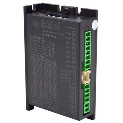
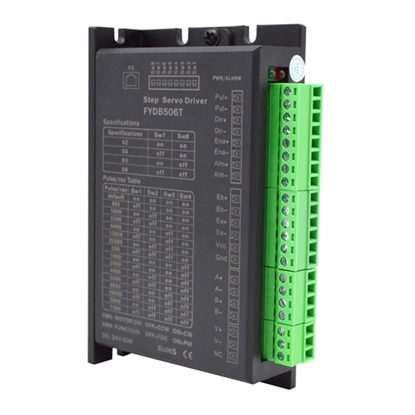
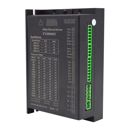
Closed Loop Stepper Motor Driver, 2 Phase, 0.1A ~ 4A
Closed Loop Stepper Motor Driver, 2 Phase, 1A ~ 6A
Closed Loop Stepper Motor Driver, 2 Phase, 2A ~ 8A
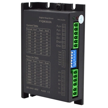
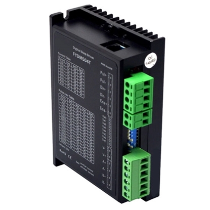
Digital Stepper Motor Driver, 2 Phase, DC 18V ~ 36V
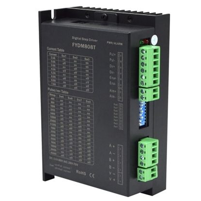
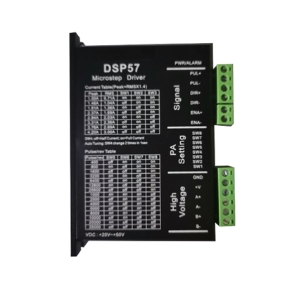
Digital Stepper Motor Driver, 2 Phase, DC 24V ~ 50V
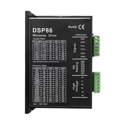
Digital Stepper Motor Driver, 2 Phase, DC 24V ~ 80V
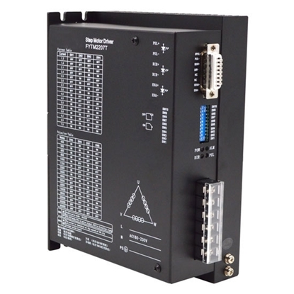
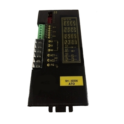
Digital Stepper Motor Driver, 3 Phase, AC 180V ~ 230V
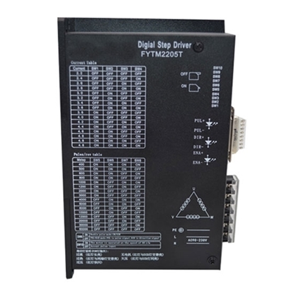
Digital Stepper Motor Driver, 3 phase, AC 90V ~ 230V
2-phase Digital Stepper Driver for Nema 11, 14, 17 Stepper Motor
Bipolar Stepper Driver for 2 phase Nema 23, 34 Stepper Motor
Bipolar Stepper Motor Driver, 2 phase, DC 20-30V
DC Digital Stepper Motor Driver 1-4.2A 20-50V, 2 phase
Digital Stepper Driver 1-4.2A 20-50V DC for Nema 17, 23 Stepper Motor
Digital Stepper Driver 2-6A for Nema 23, 34, 42 Stepper Motor
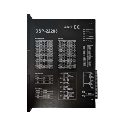
Digital Stepper Driver 80-220V AC for Nema 34 Stepper Motor
Digital Stepper Driver for 3 phase Nema 34, 42 Stepper Motor
Digital Stepper Motor Driver, 2 phase , DC 24-70V
Digital Stepper Motor Driver, 3 phase, AC 100V-220V, 2-7.5A
Microstep Driver 20-50V for 2 phase Nema 17, 23 Stepper Motor
Stepper driver is an actuator which can transform pulse signal into angular displacement signal. The performance of the stepper system is not only up to the motor, but also depends on the stepper driver.
ATO offers best quality stepper motor drivers at the best price, including 2 phase and 3 phase digital stepper driver. AC power supply and DC power supply are available. Our stepper driver are used to drive 2-phase and 3-phase Nema 11, 14, 17, 23, 24, 34, 42 stepper motors. Buy a low cost stepper driver on ATO now.
Subdivision of Stepper Motor Driver Principle
A stepper motor is equipped with a permanent magnet rotor, and the stator has at least two windings. When the rotor is magnetically aligned with the stator winding, the second winding will be driven. The two windings turn on and off alternately, which will cause the motor to lock in the desired step position. The direction of current flow through the windings can also be reversed.
In a stepper motor with two stator windings, there are four steps separated by 90°. According to the pulses supplied to the stator winding, the steps of the movement of the stepper motor can be precisely controlled. The speed control of the stepper motor can be achieved by supplying a pulse frequency to the winding, while the direction of rotation can be changed by reversing the pulse train. The pole pieces inside the motor have many teeth that help locate the rotor relative to the stator. Some stepper motors also have teeth on the stator stages. Depending on the control technology used, stepper motors can be controlled in full, half, or microstepping.
The subdivision control of the stepper servo motor is realized by the driver accurately controlling the phase current of the stepper motor. Taking a two-phase motor as an example, if the rated phase current of the motor is 3A, if a conventional driver (such as the commonly used constant current chopper is used) Wave mode) to drive the motor, the current in the windings will change from 0 to 3A or from 3A to 0 every time the motor runs. The huge change of phase current will inevitably cause vibration and noise of the motor. If a subdivided driver is used to drive the motor in a state of 10 subdivisions, the current in the windings changes by only 0.3A instead of 3A for each microstep of the motor, and the current changes in a sinusoidal pattern, which greatly increases the vibration and noise of the motor are improved, so the performance advantage is the real advantage of the subdivision. Since the subdivision driver needs to precisely control the phase current of the motor, the driver must have very high technical requirements and process requirements, and the cost will also be high.
Subdivision of stepper motor driver 1: "Smoothing" does not precisely control the phase current of the motor, but only slows down the rate of change of the current, so "smoothing" does not generate microsteps, and subdivided microsteps can be used for precise positioning.
Subdivision of stepper motor driver 2: After the phase current of the motor is smoothed, it will cause a decrease in the motor torque, and the subdivision control will not cause a decrease in the motor torque, on the contrary, the torque will increase.
How to Set the Subdivision of Stepper Motor Driver?
- Usually the higher the number of subdivisions, the higher the control resolution. However, if the subdivision number is too high, the feed rate will be affected. Generally speaking, for users with high precision requirements, the pulse equivalent can be considered as 0.001mm/P (the feed speed is 9600mm/min at this time) or 0.0005mm/P (the feed speed is 4800mm/min at this time); for precision requirements For users who are not high, the pulse equivalent can be set larger, such as 0.002mm/P (the feed speed is 19200mm/min at this time) or 0.005mm/P (the feed speed at this time is 48000mm/min). For a two-phase stepping motor, the calculation method of pulse equivalent is as follows: pulse equivalent = lead screw pitch ÷ subdivision ÷ 200.
- Take-off speed: This parameter corresponds to the take-off frequency of the stepper motor. The so-called take-off frequency is the frequency at which the stepper motor can directly start working without acceleration. Reasonable selection of this parameter can improve the processing efficiency, and can avoid the low-speed section with poor motion characteristics of the stepping motor; however, if the parameter is selected too large, it will cause boring, so it must be left over. In the factory parameters of the motor, the jump frequency parameter is generally included. However, after the machine tool is assembled, this value may change and generally decrease, especially when performing motion with load. Therefore, this setting parameter is determined by actual measurement after referring to the factory parameters of the motor.
- Single-axis acceleration: This is used to describe the acceleration and deceleration capability of a single feed axis, in mm/sec squared. This index is determined by the physical characteristics of the machine tool, such as the mass of the moving part, the torque of the feed motor, the resistance, the cutting load, etc. The larger this value is, the less time is spent in the acceleration and deceleration process during the movement, and the higher the efficiency. Typically, for stepper motors, this value is between 100 ~ 500, and for servo motor systems, it can be set between 400 ~ 1200. During the setting process, start with a small setting, run for a period of time, repeat various typical movements, pay attention to observation, and then gradually increase if there is no abnormality. If an abnormal situation is found, reduce the value and leave a 50%~100% insurance margin.
- Curve acceleration: It is used to describe the acceleration and deceleration capability of multiple feed axes in linkage, the unit is mm/sec squared. It determines the speed of the machine tool when doing circular motion. The larger this value is, the higher the allowable speed of the machine tool when performing circular motion. Usually, for a machine tool composed of a stepper motor system, the value is between 400 and 1000, and for a servo motor system, it can be set between 1000 and 5000. In the case of heavy machine tools, this value is smaller. During the setting process, start with a smaller setting, run for a period of time, repeat various typical linkage movements, and observe carefully. If there is no abnormality, then gradually increase. If an abnormal situation is found, reduce the value and leave a 50%~100% insurance margin.
- According to the installation positions of the three axis zero point sensors, set the parameters for returning to the mechanical origin in the manufacturer's parameters. When the settings are correct, you can run "Back to Mechanical Origin" in the "Operation" menu. First return to the single axis. If the movement direction is correct, continue to return. Otherwise, stop and reset the direction of returning to the machine origin in the manufacturer's parameters until all axes can return to the machine origin.
- Set the automatic refueling parameters (set smaller, such as filling oil every 5 seconds), observe whether the automatic refueling is correct, if it is correct, set the automatic refueling parameters to the actual required parameters.
- Whether the set value of electronic gear and pulse equivalent match. You can make a mark on any axis of the machine tool, set the coordinate of this point as the working zero point in the software, use the direct input command, jog or handwheel and other working methods to make the axis travel a fixed distance, and use the vernier caliper to measure the actual distance. Whether it is consistent with the distance displayed by the coordinates in the software.
Difference between Stepper Motor Driver and Servo Motor Driver
Stepper motor driver: It is an electronic product that can send out uniform pulse signals. After the signal it sends enters the stepper motor driver, it will be converted by the driver into a strong current signal required by the stepper motor to drive the stepper motor to run. The stepper motor controller can accurately control the stepper motor to rotate through every angle. What the driver receives is a pulse signal. Every time a pulse is received, the driver will give a pulse to the motor to make the motor rotate at a fixed angle. Because of this feature, stepper motors are widely used in various industries.
Servo drive: It is a controller used to control servo motors. Its function is similar to that of frequency converters acting on ordinary AC motors. The servo motor driver is part of the servo system and is mainly used in high-precision positioning systems. Generally, the servo motor is controlled by three methods of position, speed and torque to achieve high-precision positioning of the transmission system. It is currently a high-end product of transmission technology.

