Safety Relay
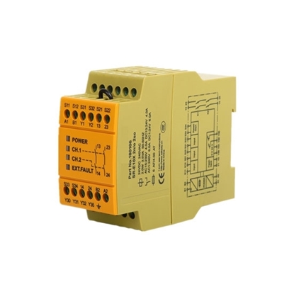
Safety Relay 24V AC/DC 2NO
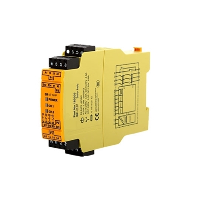
Safety Relay 24V AC/DC 3NO+1NC
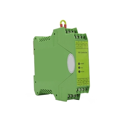
Safety Relay for Safety Mat, One-to-one, 24VDC
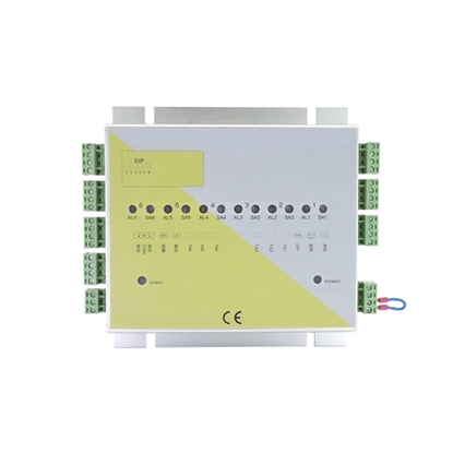
Safety Relay for Safety Mat, One-to-six, 24VDC
Safety relay is used to form a safety circuit and has a mandatory guiding structure, which can detect the failure of the junction fusion. ATO safety relay 24V DC provides you with a safe solution, compact design, flexible application, is the ideal choice.
What is a Safety Relay?
Safety relay can be classified into electromagnetic safety relay, thermal reed relay and solid-state relay. The working principle of safety relays can also be roughly divided into three types. Safety relay is composed of several relays and circuits, so as to supplement each other's abnormal defects and achieve the complete function of relay with correct and low faulty operation, so as to make the error and failure value become lower, thus reaching higher safety factor. Therefore, multiple safety relays should be designed to protect different grades of machinery. It is used to mainly protect the mechanical operators who perform operation under different levels of risk.
Where is the Safety Relay Used?
- When the emergency stopping is released, the machine cannot start suddenly.
- When failure of the machine safety circuit occurs, the power supply of machine can be stopped.
- When the safety circuit fails, the machine cannot start the safe input such as safety switch and light screen.
Difference between Safety Relay and Common Relay
Safety relay and common relay have different external dimensions. Main differences between a safety relay and a general relay are as follows: The so-called safety relay doesn't mean a relay without fault, but the relay makes regular actions when a fault occurs. It has a mandatory steering contact structure that ensures safety in case of contact fusion, which is completely different from the common relay.
The so-called safety relay doesn't mean a relay without fault, but the relay makes regular actions when a fault occurs. It has a mandatory steering contact structure that ensures safety in case of contact fusion, which is completely different from the common relay.
How to Use a Safety Relay?
Measure the contact resistance, measure the resistance between normally closed contact and movable contact with the resistance band of a multimeter, corresponding resistance shall be 0 (the contact resistance can be measured within 100 millieu in a more precise way), but the resistance between normally open contact and movable contact shall be infinitely great. On this basis, the normally closed contact and normally open contact can be distinguished.
Measure coil resistance, resistance of a power relay coil can be measured with the R×10Ω band, thus judging whether the coil has open circuit. Measure actuation voltage and actuation current, with an adjustable stabilized voltage supply and ammeter, the power relay can be input with a voltage while the ammeter can be connected in series to monitor. Slowly increase the power supply. Voltage and record the actuation voltage and actuation current when the power relay is attracted. For accuracy, more operations can be repeated to get the average value. Measure release voltage and release current, connect wires as the test above. When the power relay is attracted, reduce the power supply voltage slowly and record the voltage and current as hearing the relay to release again. More operations can be repeated to get the average value.
How to Measure the Safety Relay?
Measure the DC resistance of safety safety relay coil
Measurement method of a safety relay's DC resistance with a digital multiemter is similar to that with a pointer multimeter. According to the nominal DC resistance of safety relay, place the multimeter in an appropriate resistor and connect two test pens to the leading wire of the safety relay coil, then measure the resistance. Comparing the measurement result with the nominal resistance, if the error is within ±l0%, it's normal. If the resistance is obviously smaller, partial short-circuit fault exists in the coil; If the resistance is zero, the coil is short circuited; If the multiemter shows "1", the coil breaks.
Measure the actuation current
Actuation current is measured as the same as a pointer multimeter, namely placing the digital multiemter at 200mA DC band, then connecting it in series with the safety relay coil, a 5.1kΩ potentiometer and 200Ω resistor, connecting them with a 20V power supply.
Measure the release current
After measuring the attract current, keep the circuit unchanged and measure the release current. When measuring, adjust the potentiometer slowly to increase its resistance while the safety relay is attracted, when the safety relay is about to release, the current shown on the multimeter shall be the release current.
Measure the contact resistance
Measure the resistance between two closed contacts with the 200Ω omh band of the multimeter. Generally, the resistance shall be near zero. If the multiemter shows "1", that means the two contacts are disconnected.


