Flow Switch
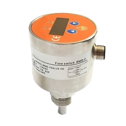
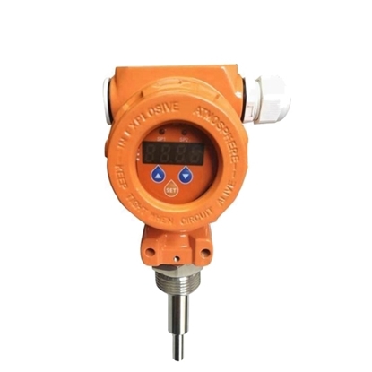
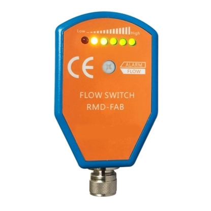
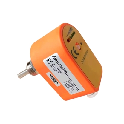
Thermal Dispersion Air Flow Switch, M18/ G1 Thread
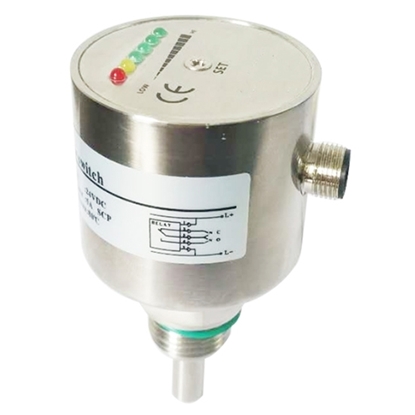
Thermal Dispersion Flow Switch, G1/2 or G1/4 Thread
Thermal Dispersion Gas Flow Switch, PNP/ NPN
Thermal Dispersion Liquid Flow Switch, 24VDC/ 220VAC
Thermal Dispersion Water Flow Switch, Relay/ 4-20mA
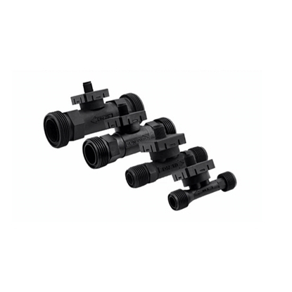
G1/4" Magnetic Water Flow Switch
G1/2" Magnetic Water Flow Switch
G3/4" Magnetic Water Flow Switch
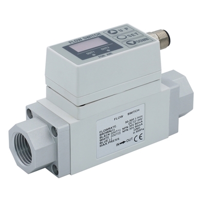
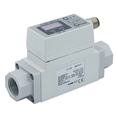
3/8" Digital Flow Switch for Air
1/2" Digital Flow Switch for Air
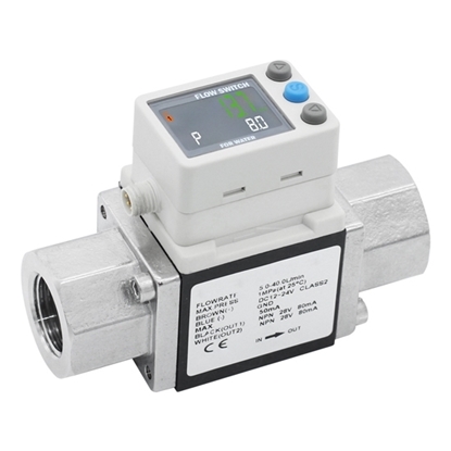
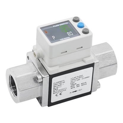
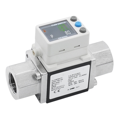
3/8" Digital Flow Switch for Water
1/2" Digital Flow Switch for Water
3/4" Digital Flow Switch for Water
1" Digital Flow Switch for Water
Air Flow Sensor, Thermal Flow Sensor
Gas Flow Sensor for Air/Nitrogen/Oxygen
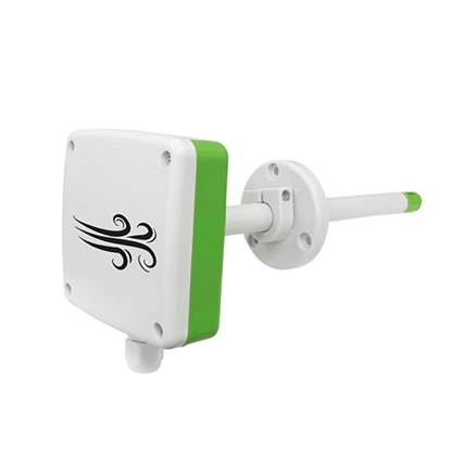
Duct Air Flow Sensor, RS485/4-20mA/0-5V/0-10V
Vortex Flow Sensor, 0.5-150 L/min, DN6/DN10/DN20/DN25
The flow switch is mainly installed online or plug-in in the water, gas, oil and other media pipelines. When the flow is higher or lower than a certain value, the switch will be triggered to output an alarm signal, and the system can take the corresponding action after obtaining the signal. Common flow switches mainly include piston flow switches, thermal dispersion flow switches, electronic flow switches, etc. Compared with traditional vane type flow switches and piston flow switches, the air/ water/ oil flow switches have higher sensitivity. Because the installation position of the thermal dispersion flow switch is not restricted, there is no wear of the movable mechanical structure, and the liquid containing impurities can be measured. And when you buy a thermal dispersion flow switch from ATO, you can choose different materials to measure the environment of different acid and alkaline liquids. They are all suitable for hydroelectric power generation, refrigeration and air conditioning, electronics, chemistry, shipbuilding, food, pharmaceuticals, optics, semiconductors and other industries. In addition, ATO.com also provides 1/4 inch, 1/2 inch, 3/4 inch 3/8 inch and 1 inch water and air flow switches for your applications.
Water Flow Switch Working principle
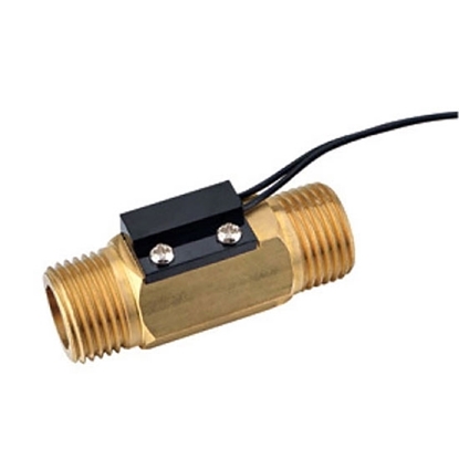
When there is water flowing in the water flow switch, and the water flow rate is greater than or equal to 1.0 liters per minute, the magnetic core in the water flow switch is displaced by the water flow, and the displacement of the magnetic core drives the magnetic source to produce a magnetic control effect, so that the water flow switch outputs "on" signal. The signal is input to the equipment control system, and the control system realizes the control function. When the water flow is less than the starting flow, the water flow switch outputs an "off" signal. The control system produces the opposite control action to the above. When the water flow in the pipeline is less than 1 liter per minute, the magnetic core drives the magnetic source to return under the thrust of the return spring, so that the sensor outputs a "0" switch signal and stops the system.
Thermal Dispersion Flow Switch Working Principle
Thermal dispersion flow switches are designed according to the principle of heat exchange. During the measurement, heat is generated by the heating module. If there is no medium flowing in the pipe, the heat received by the thermal sensing module is a fixed value. When there is a medium flowing, the heat received by the thermal sensor module will change with the change of the medium flow rate. The thermal sensor module converts the temperature difference signal into an electrical signal, and then converts it into a corresponding standard analog signal or contact through the processor signal is output. The thermal dispersion flow switch displays and controls the flow of the medium through this signal. Thermal air water flow switch consists of two temperature sensors, power supply, signal processor and output relay or NPN/PNP transistor output. The voltage drop of these sensors is proportional to temperature and operates accurately over a wide temperature range. Heat one of the sensors above the medium temperature. The other sensor has the same temperature as the medium. Equal constant current flows through the two sensors to produce a voltage difference that is inversely proportional to the amount of heat absorbed by the medium on the first sensor. Since the flow rate of the medium is proportional to the heat taken away, by measuring the voltage difference between the two sensors, the flow rate of the medium at this time can be known, and the flow rate of the medium can be known by calculation.
Flow Switch Function Testing
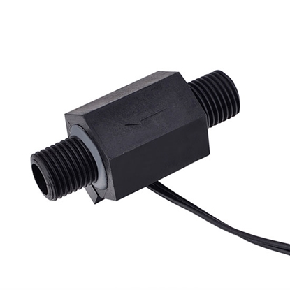
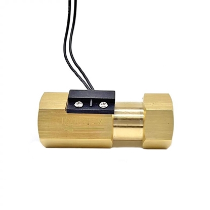
The water flowing through the plastic valve core enables the onboard permanent magnet to approach the transducer on the external black switch for the purpose of sending signals. When there is no water flow or there is obstruction that stops water flowing through the switch, the two magnets located inside the flow switch will produce a repulsive force which serves to reset the switch. To put it simply, whether there is a signal output from the flow switch depends on whether there is water flow through the switch, and this is the working mechanism of the NO switch.
The magnetic water flow switch from ATO features G1/2" of joint size at both ends. Here we prepare two pagoda joints for the ease of joining up the water pipe and the switch. With the water pipe part done, we can join together the magnetic water flow switch and other necessary components according to the control circuit diagram. The on-off of the relay is controlled by the magnetic water flow switch. The warning light is controlled by the normally closed contacts of the relay.
If you want to know more about flow switch, please click this video.
Flow Switch Application
Flow switches are used to monitor and control the flow of fluids in industrial process systems. Automated industrial systems that handle fluid media rely heavily on flow switches to ensure safe and optimal flow. Flow switches respond to pre-set flow levels, and when those levels are reached, the flow switch has two functions, including closing the contacts, causing a particular device to open, or opening the contacts, causing a particular device to close.
What are the Types of Flow Switches?
- Gas flow switch: It is suitable for media such as air and steam. They are commonly used in HVAC applications.
- Liquid Flow Switches: For use with media including water, lubricants, chemicals and slurries. They are widely used in various industrial applications.
- Volumetric Flow Switch: It is used to measure the flow of liquids or gases. This measurement is based on volume per unit of time.
- Velocity flow switch: It is used to measure the flow of moving media. This measurement is made with velocity.

