Brushed DC Motors
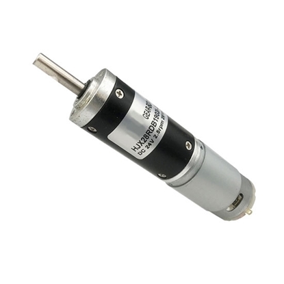
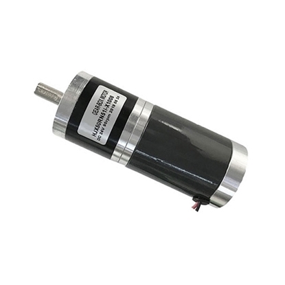
Brushed DC Motor with Gearbox, 7000rpm, 12V/24V, 28mm
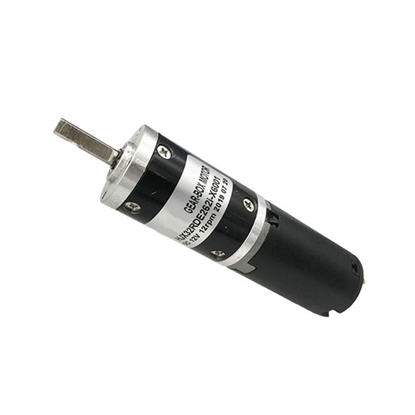
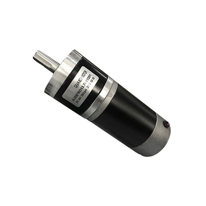
Brushed DC Motor with Gearbox, 2800rpm, 12V/24V, 32mm
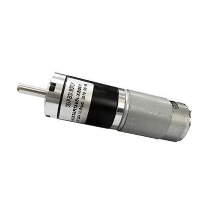
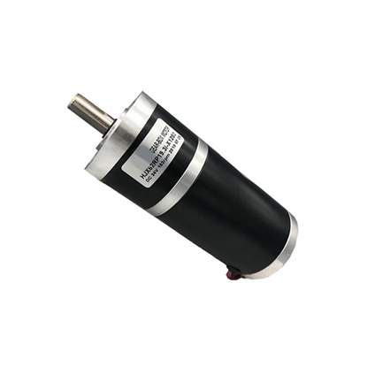
Brushed DC Motor with Gearbox, 4000rpm, 12V/24V, 36mm
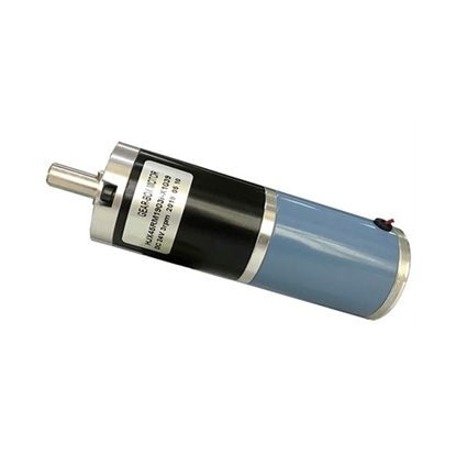
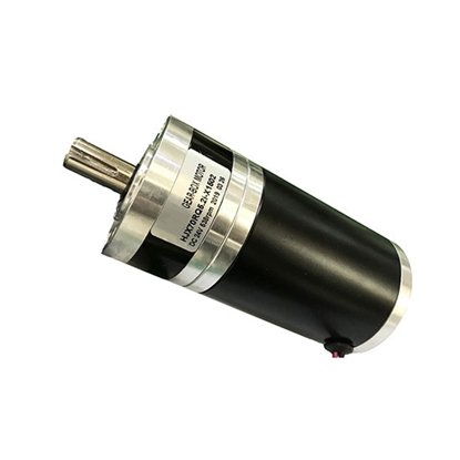
Brushed DC Motor With Gearbox, 4000rpm, 12V/24V, 45mm
Brushed DC Motor with Gearbox, 3200rpm, 12V/24V, 50mm
Brushed DC Motor with Gearbox, 3000rpm, 12V/24V, 57mm
Brushed DC Motor with Gearbox, 3200rpm, 12V/24V, 62mm
Brushed DC Motor with Gearbox, 2800rpm 12V/24V, 70mm
Brushed DC motor with gearbox is a built-in carbon brush electric gear motor with different gear ratios. It is the basis of all motors, which is simple to control circuit. ATO offers high speed and high torque BDC motor for your choices, 12V or 24V DC to operate. The gearbox diameter of 28mm to 70mm, and you can select the gear ratio from 1/3.7 to 1/139 for wide applications. Different size of brushed gear motor can reach different peak torque at maximum efficiency. Our brush DC gear motors are manufacturer directly sale with low price, buy them online now!
What is a brushed DC motor?
A brushed DC motor has permanent magnets inside its outer body and a rotating armature inside. Permanent magnets are stationary and are called stators. The rotating armature contains an electromagnet, called the rotor.
In a brushed DC motor, when current is applied to the armature, the rotor rotates 180°. To exceed the initial 180 degrees, the poles of the electromagnet must flip. As the rotor spins, the carbon brushes contact the stator, flipping the magnetic field, causing the rotor to rotate 360°.
Brushed DC motor working principle
 The DC power supply current flows along the positive pole of the power supply to the left brush, the brush and the commutator rub against each other, the current flows into the coil through the left commutator, flows out from the right side of the coil, passes through the right commutator and the right The brushes flow back to the negative terminal of the power supply, forming a closed loop.
Since the coil is in the magnetic field of the main magnetic poles (N and S in the figure), the coil will be subjected to the action of electromagnetic force. Since the direction of the current on both sides of the coil is different (the current on the left flows inward, and the current on the right flows outward), the two sides of the coil are subjected to electromagnetic forces of the same magnitude and opposite directions. These two electromagnetic forces just form an electromagnetic torque. Under the pulling of the electromagnetic torque, the coil begins to rotate. In the BDC motor, the coil is embedded in the rotor slot, and the motor starts to rotate.
The left and right commutators rotate with the shaft, and the brushes are fixed. After one rotation, the coil on the right goes to the left and the coil on the left goes to the right. However, due to the existence of the commutator, the current direction in the coil on the left is now in the direction of the current. It flows in the same direction as the current of the coil on the left, so the direction of the electromagnetic force is unchanged, and the same is true on the right. Therefore, from a spatial point of view, the direction of the electromagnetic force on the coil side at the same position is always the same, which ensures the cyclic rotation of the motor.
Because the magnetic field is different when the coil is rotated to different positions, the electromagnetic force on the coil is also changing all the time, so the coil rotates unstable, sometimes fast and slow. Therefore, several coils can be installed to ensure the uniform and stable force of the coil.
What are the components of Brushed DC motor?
Stator
The stator generates a fixed magnetic field around the rotor. This magnetic field can be generated by permanent magnets or electromagnetic windings.
Rotor/ Armature
The rotor, also called the armature, consists of one or more windings. When these windings are energized, a magnetic field is created. The poles of the rotor field will attract the opposite poles of the stator field, causing the stator to rotate. As the motor rotates, the windings are continuously energized in a different order, so the poles produced by the rotor never overlap those produced by the stator.
Carbon brushes
The function of the carbon brush device is to introduce or draw out the DC voltage and the DC current. It is mainly composed of a brush, a brush holder and a conductive copper wire. The brush is a conductive block composed of graphite or metal graphite. The tightening spring is placed on the surface of the commutator with a certain pressure, and forms a sliding contact with the surface of the commutator when rotating. The brush holder is clamped on the brush rod with a screw.
Commutator
Unlike brushless DC motors and AC induction motors, BDC electric motors do not require a controller to switch the direction of the current in the electrode windings, but the commutation of the brush DC motor windings is done mechanically. A segmented copper sleeve, called a commutator, is installed on the shaft of the BDC motor. As the motor rotates, the carbon brushes slide along the commutator, making contact with the different segments of the commutator. These segments are connected to different rotor windings, so when energized through the motor's brushes, a dynamic magnetic field is created inside the motor. It is important to note that the brushes and commutators are the most wearable parts of a BDC motor due to relative slippage between them.
Why use carbon brushes?
Because the friction between the brush and the commutator will generate a lot of heat, if the friction force is too high and the temperature is too high, the brush may be directly damaged, and the friction force will greatly reduce the rotation speed of the rotor. The carbon brush can not only conduct electricity, but also heat conduction, which greatly reduces friction. Of course, because of wear, the carbon brushes on brushed DC electric motors still need to be replaced regularly.
What does the commutator do?
The commutator is to change the direction of the current in the coil, so that the coil can always rotate. A ring is cleverly designed to keep the coils at the right distance from the permanent magnets of the stator. Change the current direction of the coil through this ring (changing the current direction of the coil changes the direction of the magnetic field of the coil). This allows the coil to keep spinning, rather than attracting each other with the permanent magnet and ending up there.

