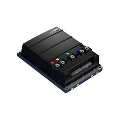
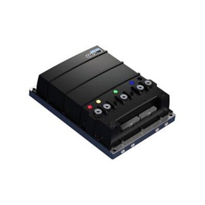
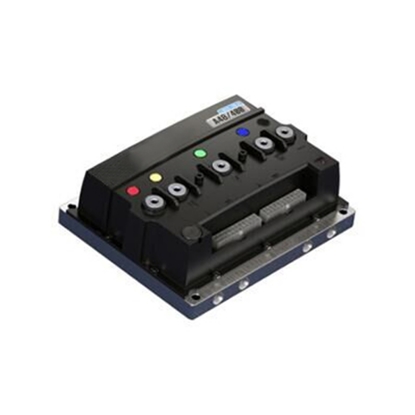
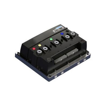
BLDC Motor Controllers
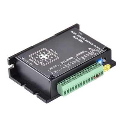
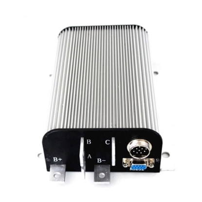
12V-30V Brushless DC Motor Controller for 12V/24V BLDC Motor
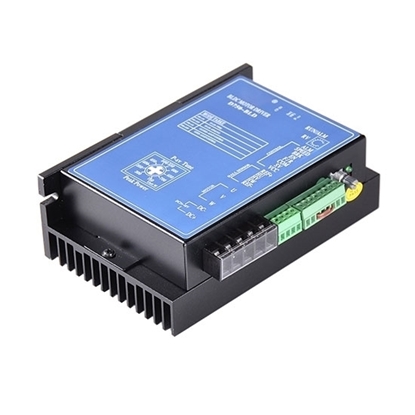
12V-56V Brushless DC Motor Controller for 12/24/36/48V BLDC Motor
18V-52V Brushless DC Motor Controller for 24/36/48V BLDC Motor
24V-60V Brushless DC Motor Controller for 24/36/48/60V BLDC Motor
24V-60V Brushless DC Motor Controller for 36/48 BLDC Motor
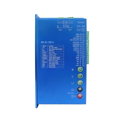
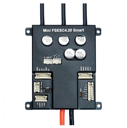
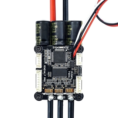
50A 3-12S Electronic Speed Controller (ESC) for Single BLDC Motor
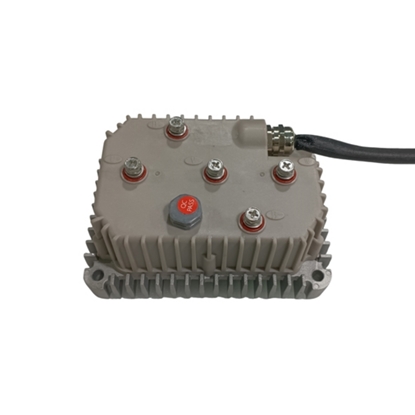
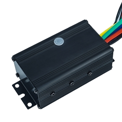
Brushless DC Motor Controller for Electric Vehicle
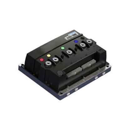
10 kW 48V BLDC Motor Controller for Electric Vehicle
10 kW 72V BLDC Motor Controller for Electric Vehicle
20 kW 72V BLDC Motor Controller for Electric Vehicle
20 kW 96V BLDC Motor Controller for Electric Vehicle
3 kW 48V BLDC Motor Controller for Electric Vehicle
5 kW 48V BLDC Motor Controller for Electric Vehicle
5 kW 96V BLDC Motor Controller for Electric Vehicle
60A 3-12S Electronic Speed Controller (ESC) for Single BLDC Motor
9V-32V Brushless DC Motor Controller for 12V/24V BLDC Motor
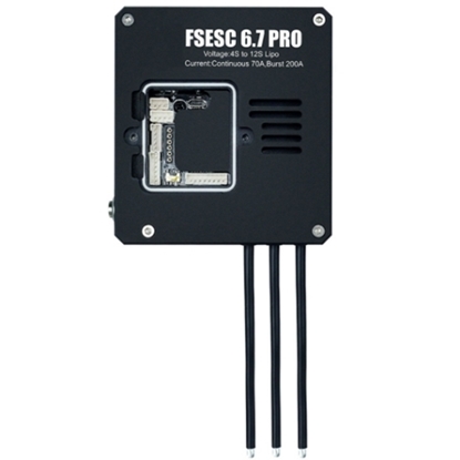
70A 4-12S Electronic Speed Controller (ESC) for Single BLDC Motor
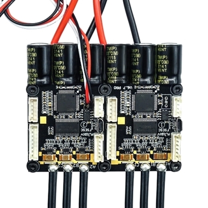
70A/140A 4-12S Electronic Speed Controller (ESC) for Dual BLDC Motor
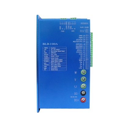
100A 4-20S Electronic Speed Controller (ESC) for Single BLDC Motor
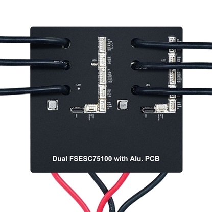
100A/200A 4-20S Electronic Speed Controller (ESC) for Dual BLDC Motor
- 1
- 2
Brushless DC motor controller, also known as BLDC motor controller, is composed of the motor main body and the driver. It has the advantages of good adjustment and starting performance of the DC motor and the simple structure of the asynchronous motor without maintenance. ATO.com offers different models of BLDC motor controllers at economical price to match with 12V, 24V, 36V, 48V 3 phase brushless motors, worm gear motors and planetary gear motors. They are compact and easy to control your motor speed.
What are the Functions of Brushless DC Motors?
The brushless DC motor controller is a control device that can be used to provide a closed-loop commutation control signal for a 3 phase brushless motor. At the same time, the mode can also be used to control the motor speed and perform the necessary protection of the motor. The brushless motor controller is much more complicated than a brushed motor controller.
Functions:
- Simple variable speed control possible.
- All important currents are determined by a single external resistor for easy setup.
- The start and stop of the motor can be done using the power supply of the circuit.
- The start-up timing sequence is completed by two capacitors.
- It can run the control function independently, and the peripheral circuit is simple.
- Adopts new back EMF commutation technology, which can provide minimum jitter-free torque.
- Efficiency control is possible.
- With commutation PLC, it can effectively suppress PWM peak noise signal.
What are the components of brushless DC motor controller?
The brushless DC motor controller is mainly composed of a single-chip microcomputer main control circuit, a power tube pre-drive circuit, an electronic commutator, a Hall signal detection circuit, a signal circuit, an under-current detection circuit, a current-limiting/over-current detection circuit, a brake signal circuit, speed limit circuit and power circuit.

Why BLDC Motor Runs with Controller?
Brushless DC motors must be equipped with corresponding controllers to rotate. This is determined by the structural principle of the brushless dc motor. The brushless DC motor replaces the mechanical commutator with an electronic commutator. It is precisely because the bldc motor uses electronic commutation, so it needs a controller to drive the circuit. The commutation circuit of the DC brushless motor consists of two parts: drive and control. The two parts are inseparable, especially low-power circuits often integrate the two to form a single application specific integrated circuit.
Brushless DC motor belongs to the category of permanent magnet stepper motors. Its performance parameters, model, power supply voltage, output power, phase angle, photoelectric switch or self-identification function must be matched with the controller of the DC brushless motor to ensure the normal operation of the bldc motor. The controller of the brushless DC motor can control the motor to start and stop, forward and reverse, adjust the speed, adjust overvoltage, overcurrent, undervoltage and other conditions. Therefore, the brushless DC motor must use a controller, otherwise the brushless DC motor will not run even if it is powered.
BLDC Motor Controller Control Speed with Analog Signal
The speed control methods of the BLDC motor controller include self-contained potentiometer speed control, external potentiometer speed control, and external analog signal speed control (0 ~ 5V). Different occasions and distances can use different speed control mode, which is one of the features of our brushless DC motor kit. Watch the video below to learn more about BLDC motor controller control speed with analog signal.
How to Maintain BLDC Motor Controller?
The quiescent current of the BLDC motor controller should normally be within 50MA. The current of the motor is generally around 1.4A at no-load speed, and some motors are around 1.8A. When the control panel does not work, the signal light on the board should flash every second/time. If the signal light does not flash without turning the handle signal, you should check:
- Whether the 5V voltage is normal, whether there is a short circuit in the external connection when it is not normal, and whether there is a short circuit on the board, etc.;
- Whether the voltage of pin 2 of the microcontroller is 5V;
- Whether the quartz crystal works;
- Whether the signal light is damaged.
Controller current and voltage adjustment.
- Current adjustment: Adjust the constantan length.
- Voltage adjustment: The undervoltage sampling circuit is composed of two voltage divider resistors from the 48V or 36V power supply to the ground. Usually, the undervoltage point can be adjusted by adjusting the resistance (Ra) connected to the power supply. Because the resistance connected to the ground is usually 1.2K, so the undervoltage value and resistance value can be calculated according to the formula: Ra = (1.2xv - 1.2 x 3) / 3
Example: When using 48V battery voltage and the value of undervoltage is 40.5V:
Ra = (1.2 x 40.5 - 1.2 x 3) / 3 ------- Ra = 15K
Note: 1.2 is the resistance connected to the ground. 3 in the formula is the AD value of the under-voltage processed by the single-chip microcomputer.
When the undervoltage value needs to be adjusted between 40.5V and 42V, when the fully loaded 1.2K resistor is connected to 82K, 39K, 36K, 33K, and 30K, the undervoltage corresponds to: 41.04V, 41.65V, 41.75V, 41.86V, 42V.

